Photo AI
Complete Table 1 to show the logic outputs for the lamps L1 and L6 - AQA - A-Level Physics - Question 2 - 2017 - Paper 8
Question 2
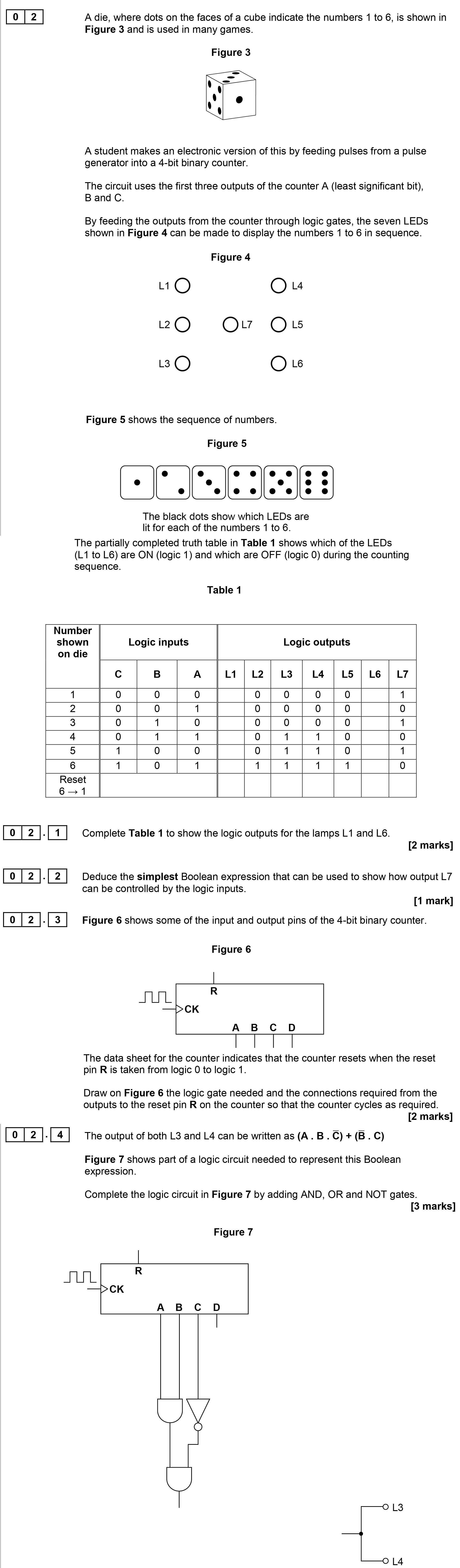
Complete Table 1 to show the logic outputs for the lamps L1 and L6. | Number shown on die | Logic inputs | Logic outputs | |---------------------|--------------|---... show full transcript
Worked Solution & Example Answer:Complete Table 1 to show the logic outputs for the lamps L1 and L6 - AQA - A-Level Physics - Question 2 - 2017 - Paper 8
Step 1

Step 2
Step 3
Draw the logic gate needed for the reset pin R
Answer
To implement the required logic for the reset pin R, a logic circuit can be designed using:
- NOT gate that takes input from B.
- A two-input AND gate that receives inputs from B and C, with its output feeding into the reset pin R.
This configuration ensures the counter resets as needed.
Step 4
Complete the logic circuit in Figure 7 by adding AND, OR and NOT gates
Answer
To complete the logic circuit:
- Add a NOT gate connected to input B.
- Add an AND gate that connects the outputs from inputs B and C.
- Connect both outputs (from the NOT gate and the AND gate) to an OR gate, which will then connect to outputs L3 and L4.
This setup allows for the proper operation of L3 and L4 based on the given conditions.