Complete Table 1 to show the logic outputs for the lamps L1 and L6 - AQA - A-Level Physics - Question 2 - 2017 - Paper 8
Question 2
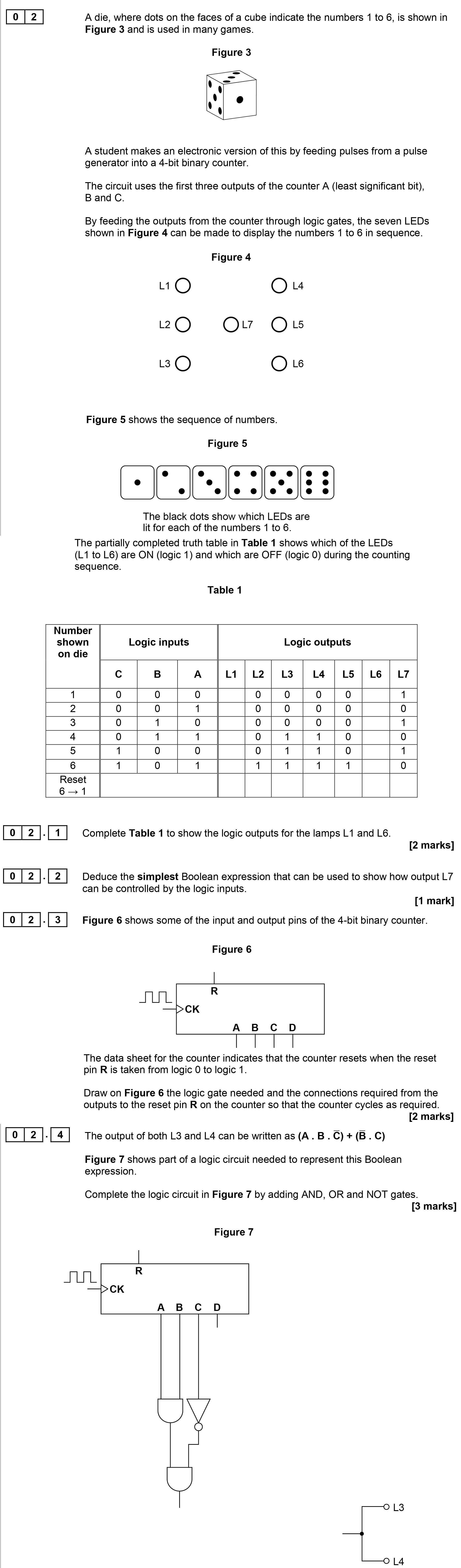
Complete Table 1 to show the logic outputs for the lamps L1 and L6.
| Number shown on die | Logic inputs | Logic outputs |
|---------------------|--------------|---... show full transcript
Worked Solution & Example Answer:Complete Table 1 to show the logic outputs for the lamps L1 and L6 - AQA - A-Level Physics - Question 2 - 2017 - Paper 8
Step 1
Complete Table 1 to show the logic outputs for the lamps L1 and L6.
96%
114 rated
Only available for registered users.
Sign up now to view full answer, or log in if you already have an account!
Answer
Number shown on die
Logic inputs
Logic outputs
B
A
---------------------
--------------
---------------
1
0
0
2
0
1
3
1
0
4
1
1
5
1
1
6
0
1
Reset 6 --> 1
Step 2
Deduce the simplest Boolean expression that can be used to show how output L7 can be controlled by the logic inputs.
99%
104 rated
Only available for registered users.
Sign up now to view full answer, or log in if you already have an account!
Answer
The simplest Boolean expression for output L7 can be represented as:
L7=NOTA
Step 3
Draw on Figure 6 the logic gate needed and the connections required from the outputs to the reset pin R on the counter so that the counter cycles as required.
96%
101 rated
Only available for registered users.
Sign up now to view full answer, or log in if you already have an account!
Answer
The logic needed includes:
A connection for the reset pin R from inputs B and C, which can be represented as an AND gate that allows resetting when both B and C are high.
Step 4
Complete the logic circuit in Figure 7 by adding AND, OR and NOT gates.
98%
120 rated
Only available for registered users.
Sign up now to view full answer, or log in if you already have an account!
Answer
Add a NOT gate from input B.
Add an AND gate connecting inputs B and C.
Connect both outputs to an OR gate, which will control the output for L3 and L4 based on the conditions.