Figure 10 shows the circuit for an infrared detector using a photodiode and an operational amplifier - AQA - A-Level Physics - Question 3 - 2021 - Paper 8
Question 3
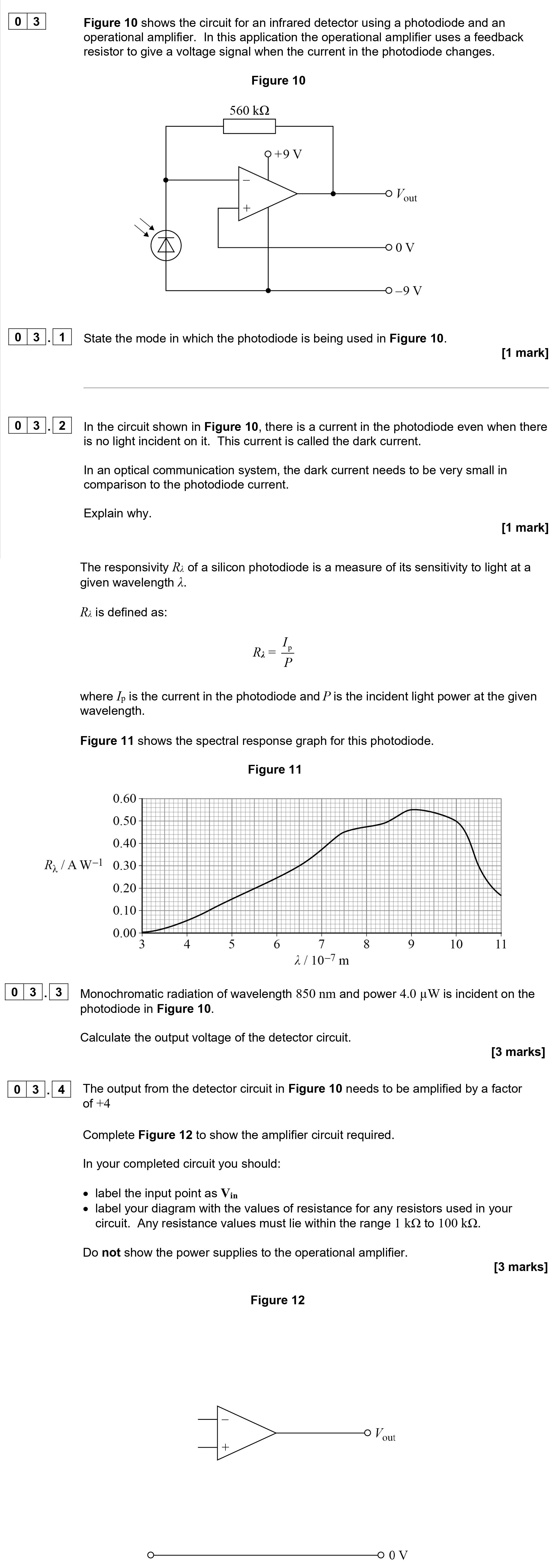
Figure 10 shows the circuit for an infrared detector using a photodiode and an operational amplifier. In this application the operational amplifier uses a feedback r... show full transcript
Worked Solution & Example Answer:Figure 10 shows the circuit for an infrared detector using a photodiode and an operational amplifier - AQA - A-Level Physics - Question 3 - 2021 - Paper 8
Step 1
State the mode in which the photodiode is being used in Figure 10.
96%
114 rated
Only available for registered users.
Sign up now to view full answer, or log in if you already have an account!
Answer
The photodiode is being used in photoconductive mode.
Step 2
Explain why the dark current needs to be very small in comparison to the photodiode current.
99%
104 rated
Only available for registered users.
Sign up now to view full answer, or log in if you already have an account!
Answer
Dark currents can contribute to noise in the system, which can reduce the signal-to-noise ratio (S/N). To maintain a high S/N, it is important to keep the dark current as low as possible relative to the photodiode current.
Step 3
Calculate the output voltage of the detector circuit.
96%
101 rated
Only available for registered users.
Sign up now to view full answer, or log in if you already have an account!
Answer
Using the defined responsivity:
At 850nm, Rλ=0.50AW−1.
The power incident on the photodiode is P=4.0μW=4.0×10⁻⁶W.
The current Ip can be calculated as follows: Ip=RλimesP=0.50AW−1×4.0×10−6W=2.0×10⁻⁶A=2.0μA.
Using the inverting amplifier gain formula: Vout=−Ip×Rf=−2.0×10−6A×560kΩ=−1.12V.
Thus, the output voltage Vout=−1.12V.
Step 4
Complete Figure 12 to show the amplifier circuit required.
98%
120 rated
Only available for registered users.
Sign up now to view full answer, or log in if you already have an account!
Answer
In Figure 12, an inverting amplifier configuration should be drawn.
Label the input point as Vin.
The feedback resistor Rf should be shown with a value around 100kΩ, and the input resistor R1 with a value around 10kΩ, maintaining the gain of +4.