Photo AI
Figure 1 shows the basic layout for a Johnson decade counter - AQA - A-Level Physics - Question 1 - 2019 - Paper 8
Question 1
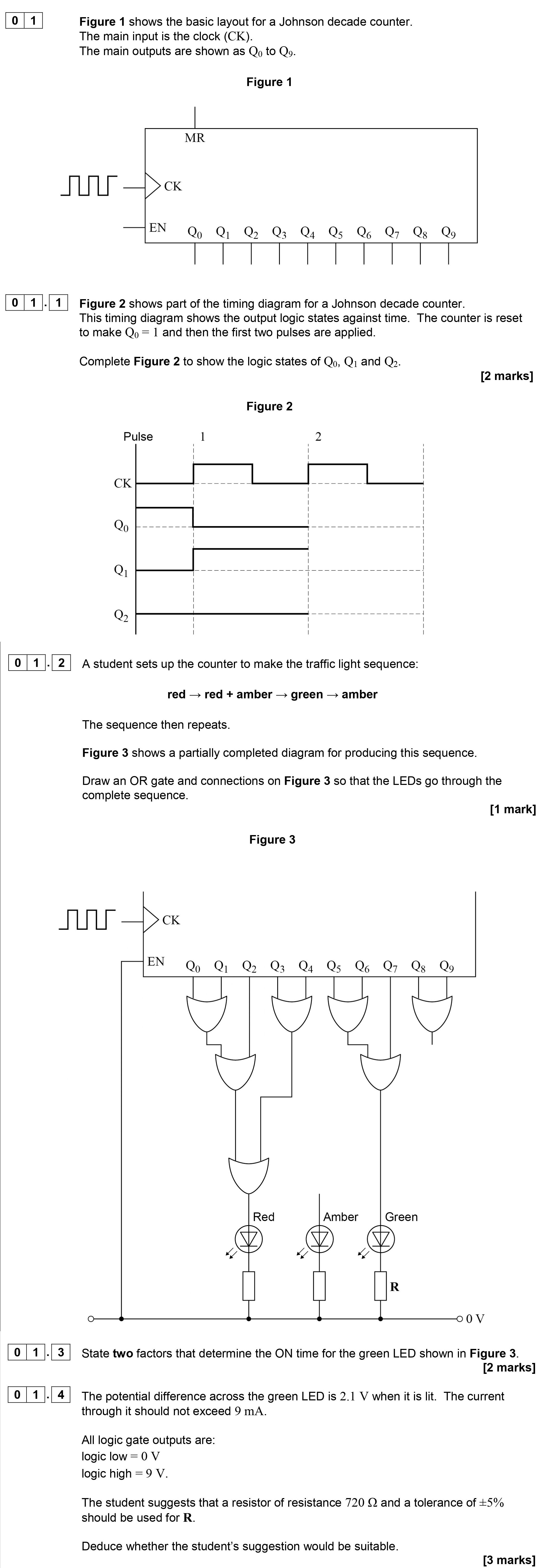
Figure 1 shows the basic layout for a Johnson decade counter. The main inputs are shown as CK. Figure 2 shows part of the timing diagram for a Johnson decade counte... show full transcript
Worked Solution & Example Answer:Figure 1 shows the basic layout for a Johnson decade counter - AQA - A-Level Physics - Question 1 - 2019 - Paper 8
Step 1
Complete Figure 2 to show the logic states of Q0, Q1 and Q2.

Answer
To complete Figure 2, we must analyze the timing diagram for the Johnson decade counter.
-
For Q0: The state of Q0 toggles with every clock pulse. Since the counter is reset to make Q0 = 1, the first clock pulse will keep Q0 at high (1 when the pulse is applied) and then toggle to low (0) at the next pulse.
-
For Q1: The state of Q1 will follow Q0 but with a delay of one clock pulse. Hence, it will be low (0) at the first pulse and high (1) at the second pulse.
-
For Q2: The state of Q2 follows after Q1. Therefore, Q2 will be high (1) after two clock pulses, which corresponds to the pulse following Q1 being high.
To summarize: In response to the first two clock pulses:
- Q0: High (1), Low (0)
- Q1: Low (0), High (1)
- Q2: Low (0), High (1)