Photo AI
Figure 6 shows a circuit containing a photodiode and an ideal operational amplifier - AQA - A-Level Physics - Question 4 - 2020 - Paper 8
Question 4
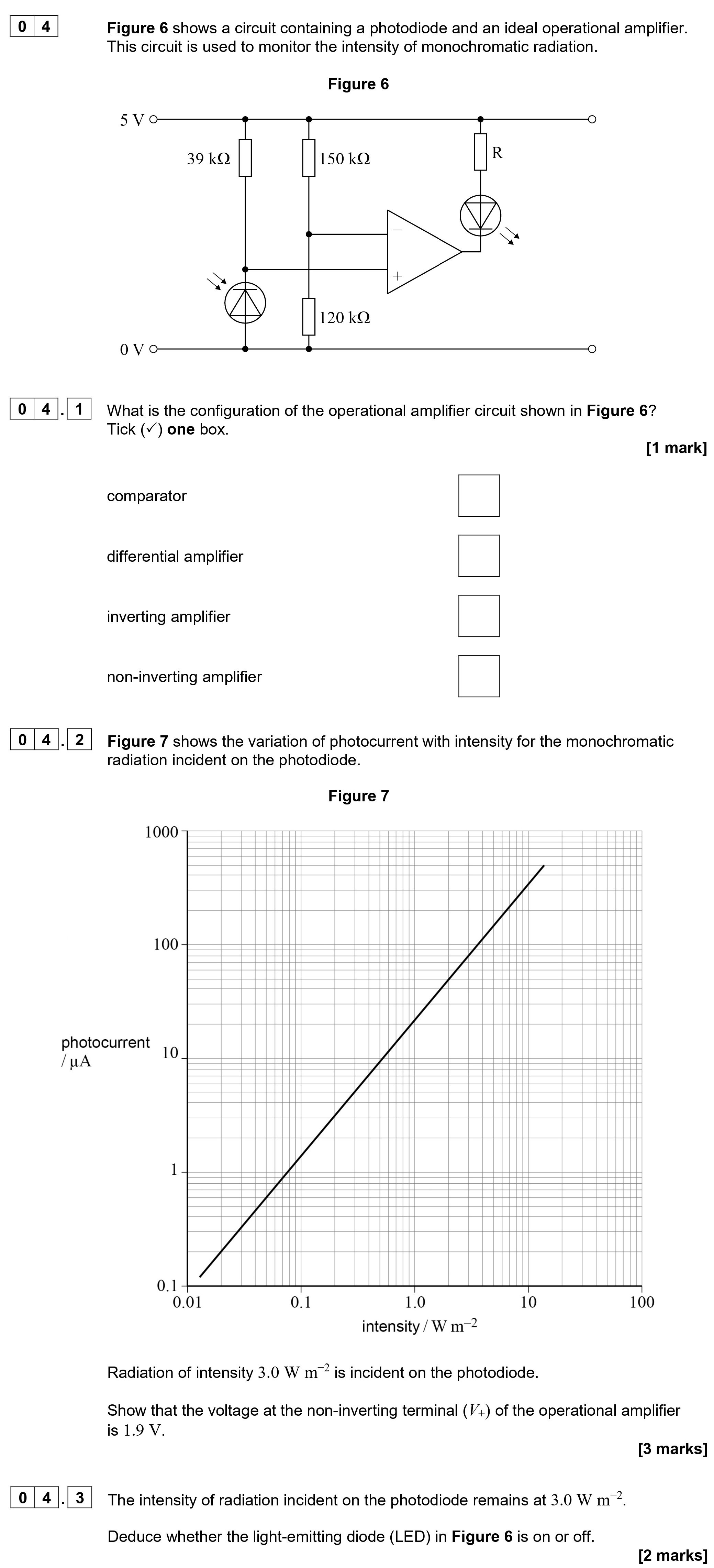
Figure 6 shows a circuit containing a photodiode and an ideal operational amplifier. This circuit is used to monitor the intensity of monochromatic radiation. **04.... show full transcript
Worked Solution & Example Answer:Figure 6 shows a circuit containing a photodiode and an ideal operational amplifier - AQA - A-Level Physics - Question 4 - 2020 - Paper 8
Step 1

Step 2
Show that the voltage at the non-inverting terminal (V<sub>+</sub>) of the operational amplifier is 1.9 V.
Answer
From Figure 7, we can see that at an intensity of 3.0 W m⁻², the corresponding photocurrent (I) is approximately 80 µA. To calculate the voltage at the non-inverting terminal (V<sub>+</sub>), we first find the voltage across the resistor:
Using Ohm's Law:
Where:
- I = 80 µA = 0.00008 A
- R = 39 kΩ = 39000 Ω
Then, the voltage at the non-inverting terminal:
For the operational amplifier to function properly, we round this to a value of approximately 1.9 V.
Step 3
Deduce whether the light-emitting diode (LED) in Figure 6 is on or off.
Answer
The intensity of radiation incident on the photodiode remains at 3.0 W m⁻², resulting in the photocurrent of 80 µA. The calculated voltage at the non-inverting terminal (V<sub>+</sub>) is 1.9 V.
For the LED to be on, the output from the operational amplifier must be high enough to forward bias the LED. Given that the voltage at the non-inverting input is greater than the inverting input, the output will be high, thus the LED will light up.