Figure 1 shows the basic layout for a Johnson decade counter - AQA - A-Level Physics - Question 1 - 2019 - Paper 8
Question 1
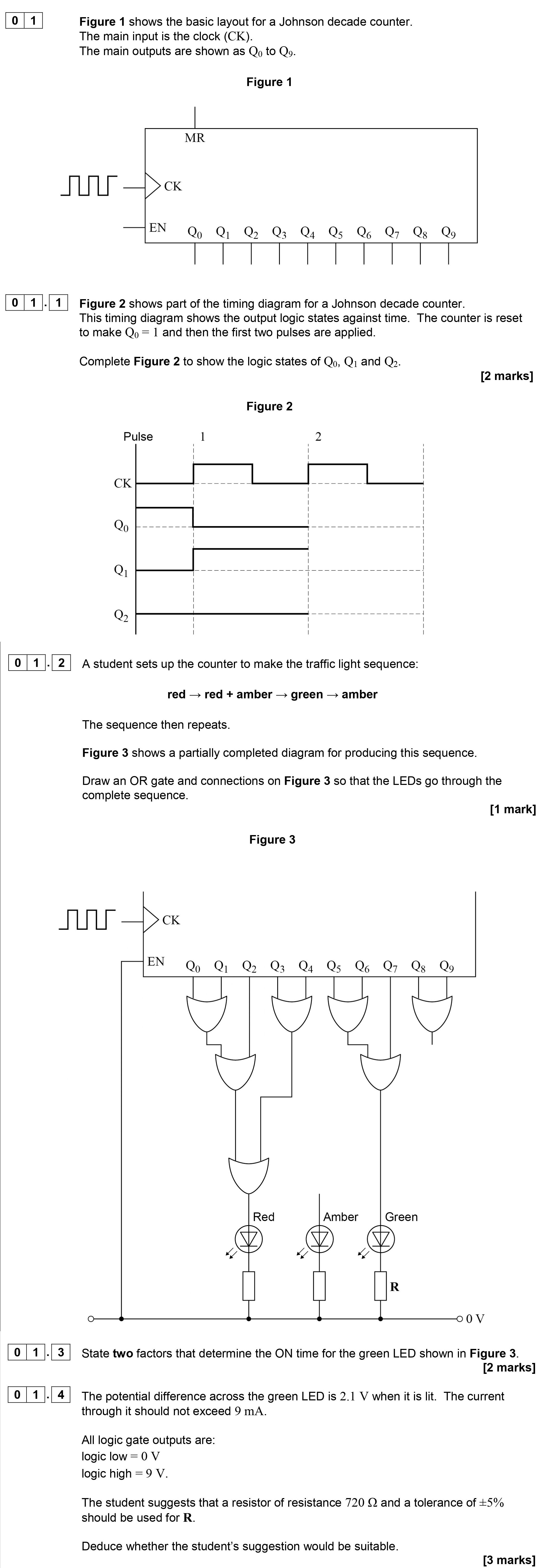
Figure 1 shows the basic layout for a Johnson decade counter. The main outputs are shown as Q0 to Q9.
Figure 2 shows part of the timing diagram for a Johnson decade... show full transcript
Worked Solution & Example Answer:Figure 1 shows the basic layout for a Johnson decade counter - AQA - A-Level Physics - Question 1 - 2019 - Paper 8
Step 1
Complete Figure 2 to show the logic states of Q0
96%
114 rated
Only available for registered users.
Sign up now to view full answer, or log in if you already have an account!
Answer
Q0 will remain high (1) for the duration of the first clock pulse. Thus, the logic state of Q0 is a flat line at logic high during this period.
Step 2
Complete Figure 2 to show the logic states of Q1
99%
104 rated
Only available for registered users.
Sign up now to view full answer, or log in if you already have an account!
Answer
Q1 will change state (low to high) as the first clock pulse ends, resulting in Q1 rising to high (1) on the first clock transition.
Step 3
Complete Figure 2 to show the logic states of Q2
96%
101 rated
Only available for registered users.
Sign up now to view full answer, or log in if you already have an account!
Answer
Q2 remains low (0) until Q1 transitions to high (1). It will change to high (1) only when Q1 is at high for the clock period.