Photo AI
Figure 10 shows the circuit for an infrared detector using a photodiode and an operational amplifier - AQA - A-Level Physics - Question 3 - 2021 - Paper 8
Question 3
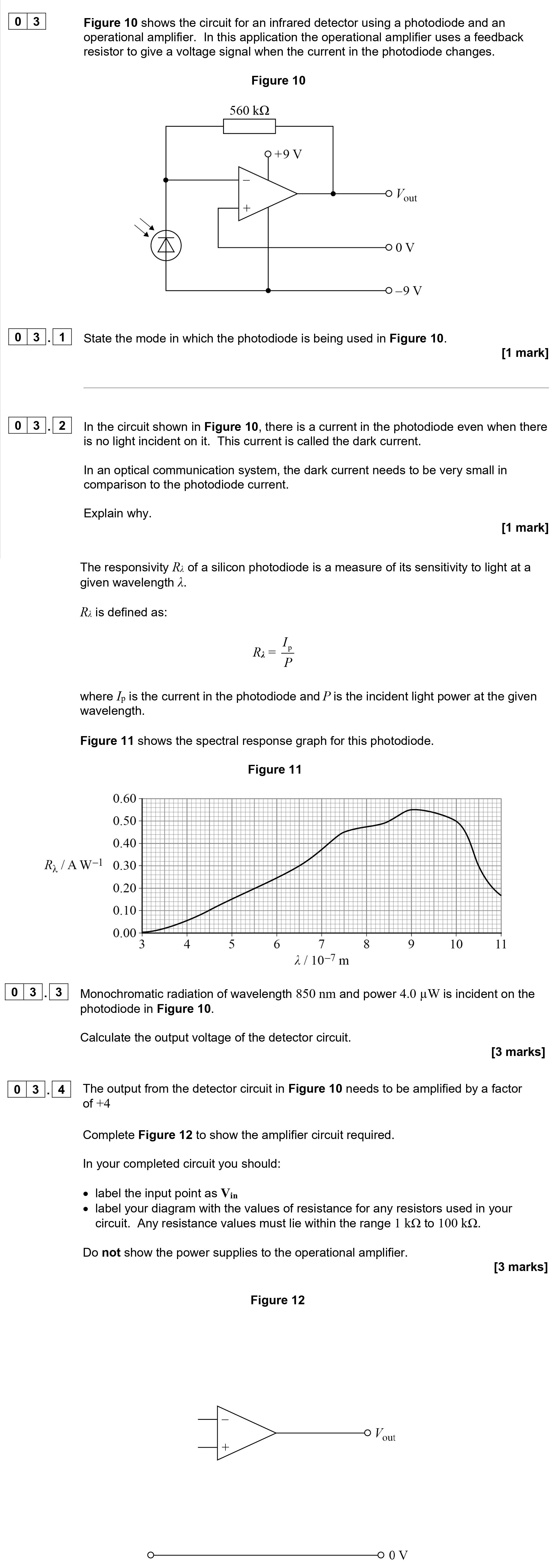
Figure 10 shows the circuit for an infrared detector using a photodiode and an operational amplifier. In this application the operational amplifier uses a feedback r... show full transcript
Worked Solution & Example Answer:Figure 10 shows the circuit for an infrared detector using a photodiode and an operational amplifier - AQA - A-Level Physics - Question 3 - 2021 - Paper 8
Step 1

Step 2
Explain why.
Answer
The dark current contributes to noise in the circuit. To ensure a high signal-to-noise ratio (S/N), especially in optical communication systems, the dark current must be kept as low as possible, ideally approaching zero when no light is present. This allows the signal from the incoming light to be distinguished clearly from any noise.
Step 3
Step 4
Complete Figure 12 to show the amplifier circuit required.
Answer
The amplifier circuit should be an inverting amplifier configuration.
- Label the input point as .
- Choose resistor values for and such that the gain is +4. This means that . For example, if we take , then . Both values lie within the 1 kΩ to 100 kΩ range.
- Draw the operational amplifier with the feedback resistor connected to the output and the input resistor connected to .