Photo AI
Figure 7 shows a circuit designed by a student to monitor temperature changes - AQA - A-Level Physics - Question 4 - 2018 - Paper 1
Question 4
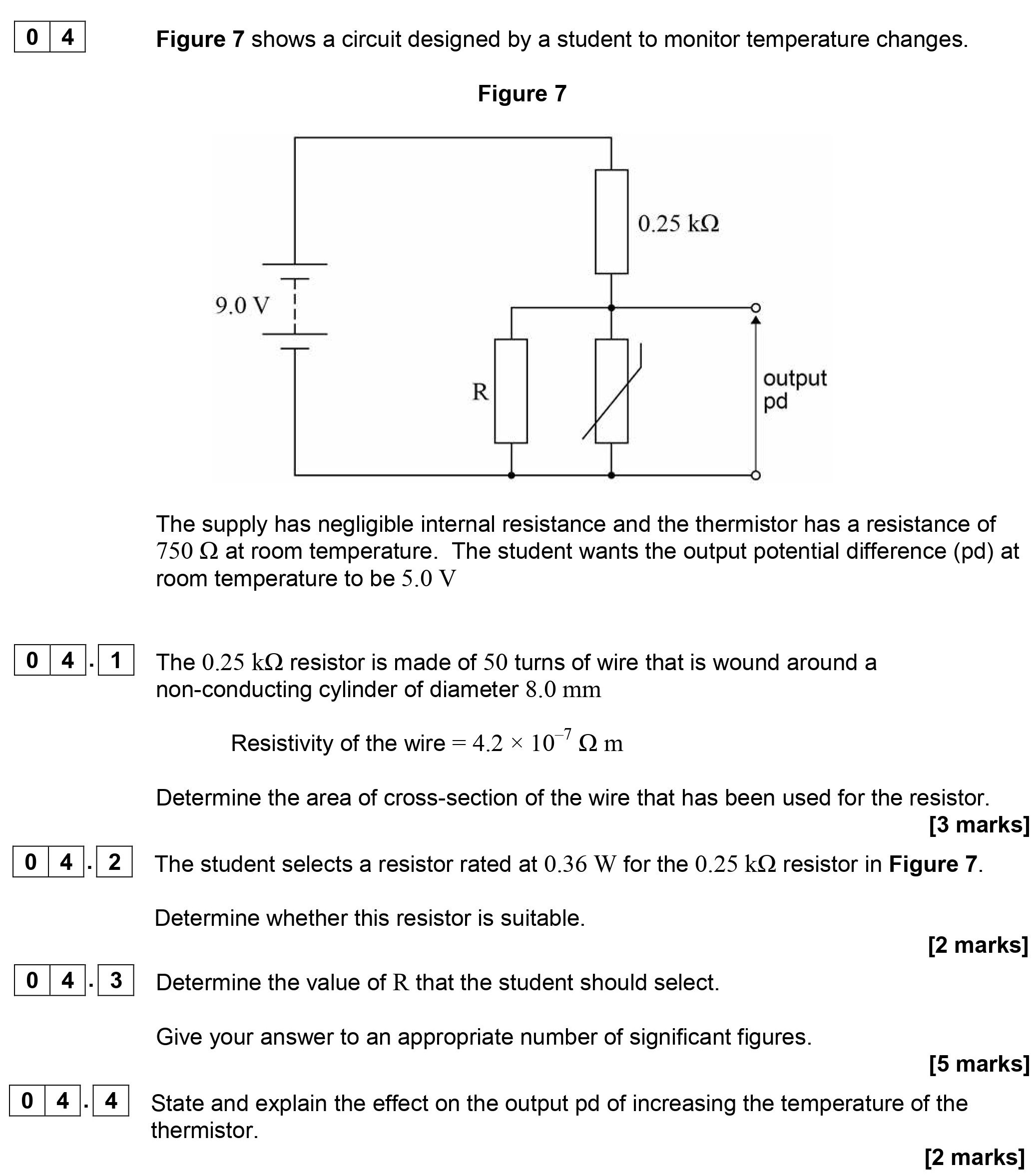
Figure 7 shows a circuit designed by a student to monitor temperature changes. The supply has negligible internal resistance and the thermistor has a resistance of ... show full transcript
Worked Solution & Example Answer:Figure 7 shows a circuit designed by a student to monitor temperature changes - AQA - A-Level Physics - Question 4 - 2018 - Paper 1
Step 1
Determine the area of cross-section of the wire that has been used for the resistor.

Answer
To determine the area of cross-section (A) of the wire, we utilize the formula for resistance:
Where:
- is the resistance (0.25 kΩ = 250 Ω)
- is the resistivity of the wire ()
- is the length of the wire
First, we find the diameter of the cylindrical wire:
To find the circumference:
Total length for 50 turns:
Rearranging the formula for area gives:
Step 2
Determine whether this resistor is suitable.
Answer
To assess the suitability, we calculate the maximum power for the 0.25 kΩ resistor, which is determined by:
Where is the supply voltage:
Since the rated power of the selected resistor is 0.36 W, it is approximately equal to the maximum power dissipation.
Thus, this resistor is deemed suitable as it can safely handle the power without exceeding its limits.
Step 3
Determine the value of R that the student should select.
Answer
Using the potential divider equation to find the value of resistance R:
Given that the desired output potential difference (pd) is 5.0 V,
We apply the equation:
Where:
Rearranging the equation gives:
Cross-multiplying to find R:
i 5R + 3750 = 9R$$
Solving yields:
ightarrow R = \frac{3750}{4} = 937.5 Ω$$Step 4
Step 5
State and explain the effect on the output pd of increasing the temperature of the thermistor.
Answer
As the temperature of the thermistor increases, its resistance decreases.
In a potential divider circuit, lowering the resistance of the thermistor will result in a higher proportion of the input voltage being dropped across the resistor R.
This leads to an increase in the output pd. Therefore, an increase in temperature will yield a higher output voltage from the circuit, affecting the intended measurements of the temperature changes monitored.