Photo AI
Figure 19 shows a lamp connected to a d.c - Edexcel - GCSE Physics - Question 8 - 2022 - Paper 1
Question 8
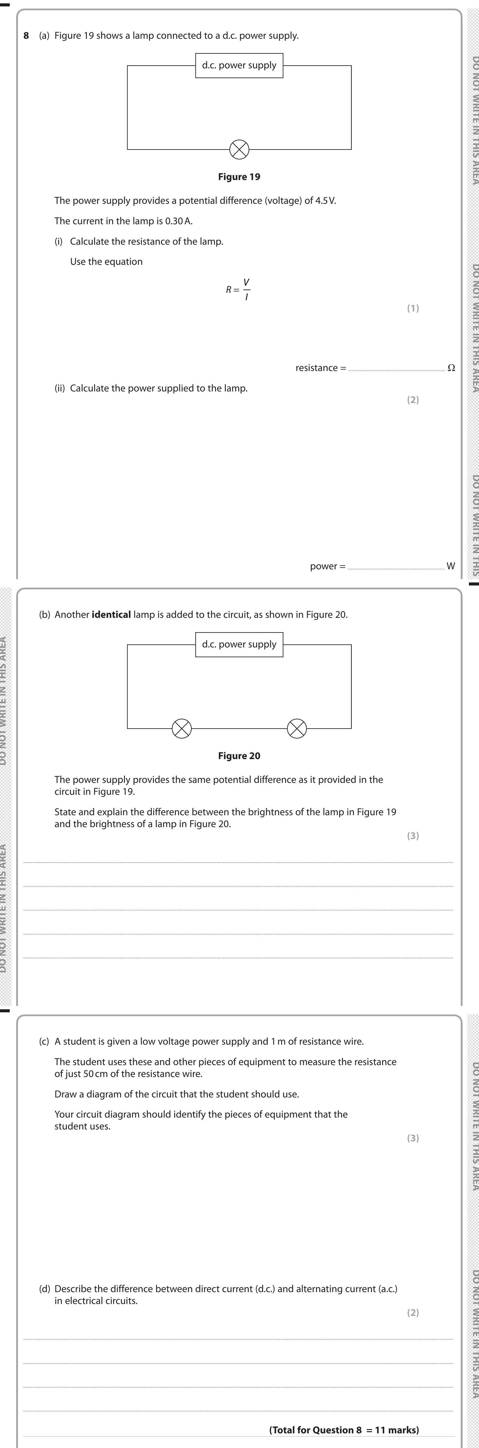
Figure 19 shows a lamp connected to a d.c. power supply. The power supply provides a potential difference (voltage) of 4.5 V. The current in the lamp is 0.30 A. (i... show full transcript
Worked Solution & Example Answer:Figure 19 shows a lamp connected to a d.c - Edexcel - GCSE Physics - Question 8 - 2022 - Paper 1
Step 1

Step 2
Step 3
State and explain the difference between the brightness of the lamp in Figure 19 and the brightness of a lamp in Figure 20.
Answer
In Figure 19, the lamp receives the full voltage from the power supply and thus glows brightly. In Figure 20, with an identical lamp added in parallel, the potential difference across each lamp remains the same as in Figure 19 (4.5 V). However, the overall resistance of the circuit decreases, meaning the total current supplied by the power source will increase, leading to each lamp having less current through them compared to a single lamp circuit.
Thus, the brightness of each lamp in Figure 20 will be dimmer than that of the lamp in Figure 19.
Step 4
Draw a diagram of the circuit that the student should use.
Answer
To measure the resistance of 50 cm of resistance wire, the student should use the following components:
- A low voltage power supply or battery.
- An ammeter to measure the current.
- A voltmeter to measure the voltage across the wire.
- The resistance wire itself.
- Connection wires or crocodile clips to securely attach the circuit elements.
The diagram should include:
- Power supply or battery symbol
- Ammeter in series with the wire
- Voltmeter in parallel across the resistance wire
- Indication that the wire length is 50 cm.
Step 5
Describe the difference between direct current (d.c.) and alternating current (a.c.) in electrical circuits.
Answer
Direct Current (d.c.) flows in one direction only, providing a constant voltage and steady current. In contrast, Alternating Current (a.c.) changes direction periodically and varies in voltage, allowing for the distribution of electrical power over long distances. This fundamental difference affects how electric devices operate and their design.