Photo AI
Last Updated Sep 27, 2025
Inverting amplifier configuration Simplified Revision Notes for A-Level AQA Physics
Revision notes with simplified explanations to understand Inverting amplifier configuration quickly and effectively.
391+ students studying
13.4.1 Inverting amplifier configuration
Inverting Amplifier Configuration:
In an inverting amplifier configuration, the output voltage from the operational amplifier (op-amp) is fed back into the inverting input. This forms a closed-loop circuit with negative feedback, allowing for control over the amplifier's gain.
Since negative feedback stabilises the output, this configuration makes it possible to set the op-amp's gain to much lower values, which is useful for controlling the amplification of signals.
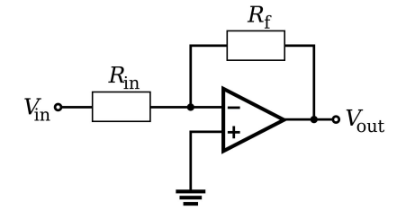
Circuit Diagram Explanation:
- The inverting amplifier circuit contains a resistor at the input and a feedback resistor connected between the output and the inverting input.
- Power supply connections (not shown in the diagram) are assumed to be present in most amplifier circuits.
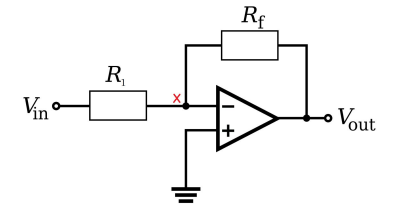
Virtual Earth Concept and Derivation:
- Virtual Earth Analysis:
- In this configuration, the non-inverting input is grounded ( V). Due to the properties of an ideal op-amp, the open-loop gain (denoted as ) is assumed to be infinite.
- This leads to the condition where the voltage at the inverting input is effectively V, called a virtual earth (or virtual ground). Although not physically connected to earth, this point is close to V due to the infinite open-loop gain.
- Transfer Function Derivation:
- Using Kirchhoff's Current Law (KCL), which states that the total current entering a junction is equal to the current leaving the junction, we can determine the relationship between input and output voltages.
- Because of the virtual earth, the input current through (from ) to the inverting input) is equal to the feedback current through (from the inverting input to ). Using Ohm's law, we have:
Since , we can write:
Rearranging, the gain (transfer function) of the inverting amplifier is given by:
This negative sign indicates inversion of the input signal's polarity.
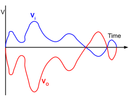
Graph of Input and Output Voltages:
The graph of the output voltage versus time shows that the output is an inverted (mirrored along the x-axis) and amplified version of the input voltage .
- Inverted Polarity: The negative sign in the gain equation reflects that the output waveform is 180° out of phase with the input.
- Reduced Distortion: The inverting configuration provides lower distortion compared to non-inverting configurations, as it benefits from stabilisation due to the virtual earth.
Key Takeaways:
- Gain: The gain of an inverting amplifier is set by the ratio .
- Phase Inversion: The output voltage is an inverted version of the input signal.
- Virtual Earth: The virtual earth condition simplifies analysis and provides stabilisation by ensuring the inverting input remains close to V.
- Applications: Commonly used in audio processing and signal conditioning, where controlled amplification with minimal distortion is desired.

500K+ Students Use These Powerful Tools to Master Inverting amplifier configuration For their A-Level Exams.
Enhance your understanding with flashcards, quizzes, and exams—designed to help you grasp key concepts, reinforce learning, and master any topic with confidence!
40 flashcards
Flashcards on Inverting amplifier configuration
Revise key concepts with interactive flashcards.
Try Physics Flashcards4 quizzes
Quizzes on Inverting amplifier configuration
Test your knowledge with fun and engaging quizzes.
Try Physics Quizzes29 questions
Exam questions on Inverting amplifier configuration
Boost your confidence with real exam questions.
Try Physics Questions27 exams created
Exam Builder on Inverting amplifier configuration
Create custom exams across topics for better practice!
Try Physics exam builder56 papers
Past Papers on Inverting amplifier configuration
Practice past papers to reinforce exam experience.
Try Physics Past PapersOther Revision Notes related to Inverting amplifier configuration you should explore
Discover More Revision Notes Related to Inverting amplifier configuration to Deepen Your Understanding and Improve Your Mastery
96%
114 rated
Operational amplifier
Non-inverting amplifier configuration
209+ studying
191KViews