6.1 Identify the type of equipment shown in FIGURE 6.1 - NSC Mechanical Technology Welding and Metalwork - Question 6 - 2016 - Paper 1
Question 6
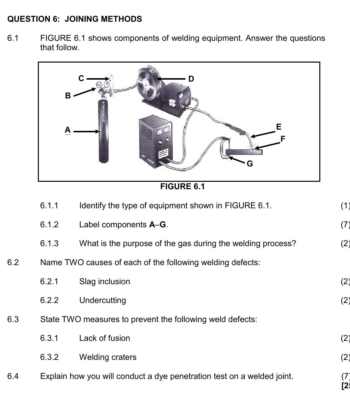
6.1 Identify the type of equipment shown in FIGURE 6.1.
6.1.2 Label components A–G.
6.1.3 What is the purpose of the gas during the welding process?
6.2 Name TWO ... show full transcript
Worked Solution & Example Answer:6.1 Identify the type of equipment shown in FIGURE 6.1 - NSC Mechanical Technology Welding and Metalwork - Question 6 - 2016 - Paper 1
Step 1
Identify the type of equipment shown in FIGURE 6.1.
96%
114 rated
Only available for registered users.
Sign up now to view full answer, or log in if you already have an account!
Answer
The equipment shown in FIGURE 6.1 is MIG/MAGS welding equipment.
Step 2
Label components A–G.
99%
104 rated
Only available for registered users.
Sign up now to view full answer, or log in if you already have an account!
Answer
A = Shielding gas cylinder
B = Regulator
C = Gas flow meter
D = Continuous wire reel
E = Welding gun
F = Arc
G = Earth clamp
Step 3
What is the purpose of the gas during the welding process?
96%
101 rated
Only available for registered users.
Sign up now to view full answer, or log in if you already have an account!
Answer
The purpose of the gas during the welding process is to prevent oxygen from coming into contact with the molten metal.
Step 4
Name TWO causes of each of the following welding defects: Slag inclusion.
98%
120 rated
Only available for registered users.
Sign up now to view full answer, or log in if you already have an account!
Answer
The included angle is too narrow.
Rapid chilling.
Step 5
Name TWO causes of each of the following welding defects: Undercutting.
97%
117 rated
Only available for registered users.
Sign up now to view full answer, or log in if you already have an account!
Answer
Faulty electrode manipulation.
Current too high.
Step 6
State TWO measures to prevent the following weld defects: Lack of fusion.
97%
121 rated
Only available for registered users.
Sign up now to view full answer, or log in if you already have an account!
Answer
Adjust the electrode angle and prepare the V groove properly.
Use proper current to ensure full fusion.
Step 7
State TWO measures to prevent the following weld defects: Weld craters.
96%
114 rated
Only available for registered users.
Sign up now to view full answer, or log in if you already have an account!
Answer
Use lower current settings.
Implement proper welding techniques.
Step 8
Explain how you will conduct a dye penetration test on a welded joint.
99%
104 rated
Only available for registered users.
Sign up now to view full answer, or log in if you already have an account!
Answer
First, clean the weld area thoroughly to remove any contaminants. Next, apply the dye to the clean surface and allow it to penetrate for a specified time. Afterward, remove any excess dye using a cleaner, followed by drying the surface. Finally, spray a developer to visualize any defects revealed by the dye.