Photo AI
A 215 mm solid concrete block wall separates two rooms on the ground floor of a dwelling house, as shown - Leaving Cert Construction Studies - Question 1 - 2018
Question 1
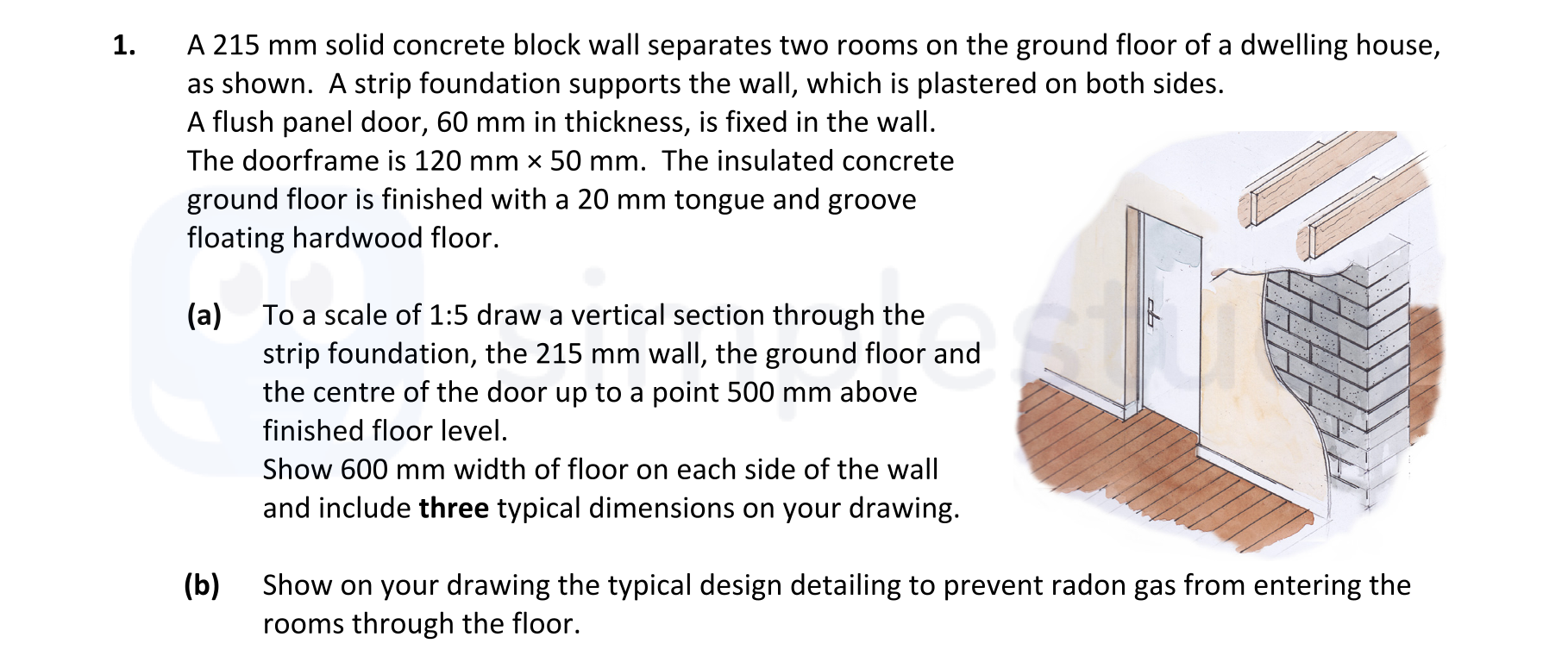
A 215 mm solid concrete block wall separates two rooms on the ground floor of a dwelling house, as shown. A strip foundation supports the wall, which is plastered on... show full transcript
Worked Solution & Example Answer:A 215 mm solid concrete block wall separates two rooms on the ground floor of a dwelling house, as shown - Leaving Cert Construction Studies - Question 1 - 2018
Step 1
To a scale of 1:5 draw a vertical section through the strip foundation, the 215 mm wall, the ground floor and the centre of the door up to a point 500 mm above finished floor level.

Answer
-
Draw the Vertical Section: Begin by sketching the section through the wall, foundation, and floor at a scale of 1:5. Show the strip foundation beneath the wall, ensuring to depict the 215 mm solid concrete block wall rising above.
-
Include the Door Section: Represent the flush panel door positioned in the wall, maintaining the 60 mm thickness and the 120 mm × 50 mm doorframe.
-
Add the Ground Floor Details: Illustrate the insulated concrete floor, ensuring to represent the 20 mm tongue and groove floating hardwood floor.
-
Mark Dimensions: Clearly indicate the height of the wall, the width of the foundation, and the overall height to the finished floor level (500 mm above the finished floor). Include a total of three typical dimensions to comply with the requirements.
Step 2
Show on your drawing the typical design detailing to prevent radon gas from entering the rooms.
Answer
-
Radon Barrier Layer: Illustrate a continuous layer of impervious material (e.g., polyethylene) placed underneath the floor to act as a radon barrier. Ensure this layer extends across the entire area under the concrete.
-
Seal Joints: Represent all joints in the gas barrier as tightly sealed using appropriate tape or sealant to prevent any gaps that could allow radon gas infiltration.
-
Drainage System: Optionally, indicate a drainage layer below the radon barrier that guides any accumulating water away from the foundation, preventing any potential degradation of the barrier from moisture.