Photo AI
A triple-glazed bay window projects 1.5 metres from the external wall of a dwelling house, as shown in the accompanying sketch - Leaving Cert Construction Studies - Question 1 - 2012
Question 1
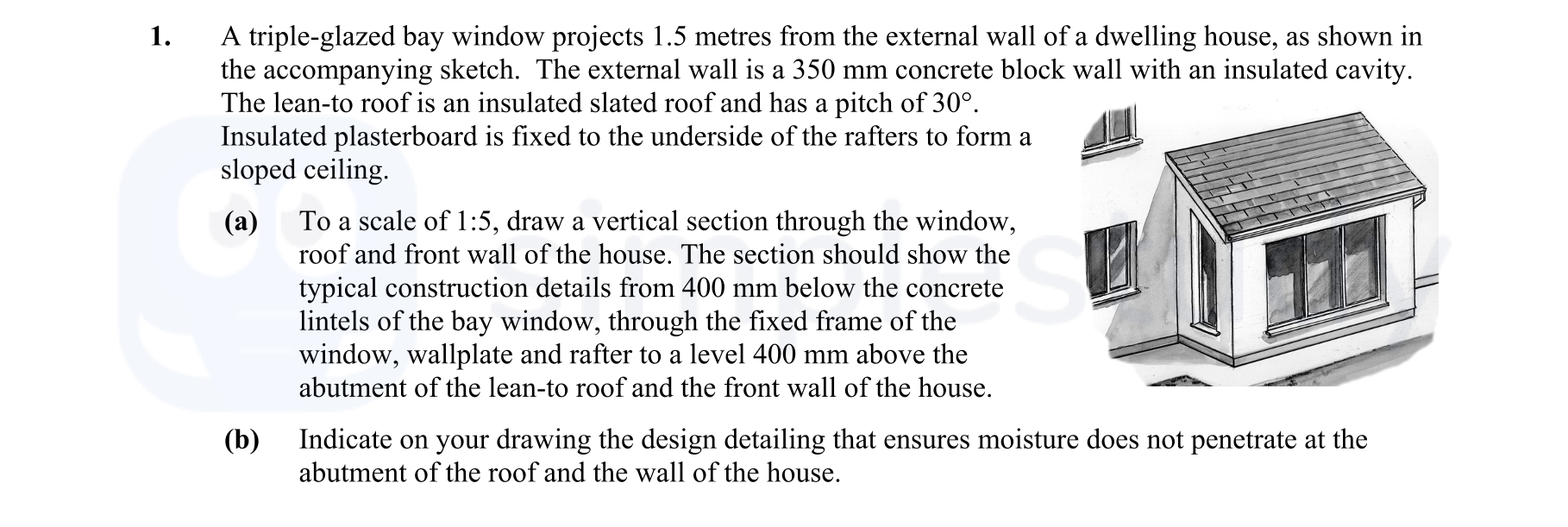
A triple-glazed bay window projects 1.5 metres from the external wall of a dwelling house, as shown in the accompanying sketch. The external wall is a 350 mm concret... show full transcript
Worked Solution & Example Answer:A triple-glazed bay window projects 1.5 metres from the external wall of a dwelling house, as shown in the accompanying sketch - Leaving Cert Construction Studies - Question 1 - 2012
Step 1
To a scale of 1:5, draw a vertical section through the window, roof and front wall of the house.

Answer
- Drawing Scale: Begin by setting up your drawing to a scale of 1:5.
- Section Line: Draw a vertical line representing the section through the window, roof, and front wall of the house.
- Window Details: Illustrate the triple-glazed bay window protruding 1.5 metres from the external wall. Indicate where the window frame meets the wall.
- Concrete Wall: Represent the 350 mm thick concrete block wall, ensuring correct proportion in relation to the window.
- Insulated Cavity: Show the insulated cavity within the concrete wall, which would be 50 mm.
- Lean-To Roof: Draw the sloping lean-to roof meeting the top of the bay window, ensuring the 30º pitch is accurately depicted.
- Rafters and Wallplate: Sketch the rafters extending from the wallplate to the roof, with insulated plasterboard fixed to their underside to form a sloped ceiling.
- Dimensions: Include dimensions such as the height from the window base to the rafter and the 400 mm distance noted in the question, ensuring to denote 400 mm above the lean-to roof abutment.
- Finalizing the Drawing: Add any remaining details like plastering or finishes to complete the vertical section.
Step 2
Indicate on your drawing the design detailing that ensures moisture does not penetrate at the abutment of the roof and the wall of the house.
Answer
- DPC Details: Include a damp-proof course (DPC) at the junction of the wall and roof to act as a barrier against moisture intrusion.
- Flashing Installation: Indicate installation of flashing along the abutment of the roof that extends into the wall, directing water away from the junction.
- Cavity Closer: Illustrate a cavity closer at the wall – extending beyond the wall’s inner layer, preventing moisture from seeping in.
- Sealing: Show the use of sealant around the perimeter where the roof abuts the wall. This provides an additional layer of protection.
- Ventilation: Ensure to mention ventilation details, if applicable, to inhibit dampness accumulation and condensation at the junction.