The 3D graphic on the right shows a machine for baling recyclable cardboard - Leaving Cert DCG - Question C-4 - 2013
Question C-4
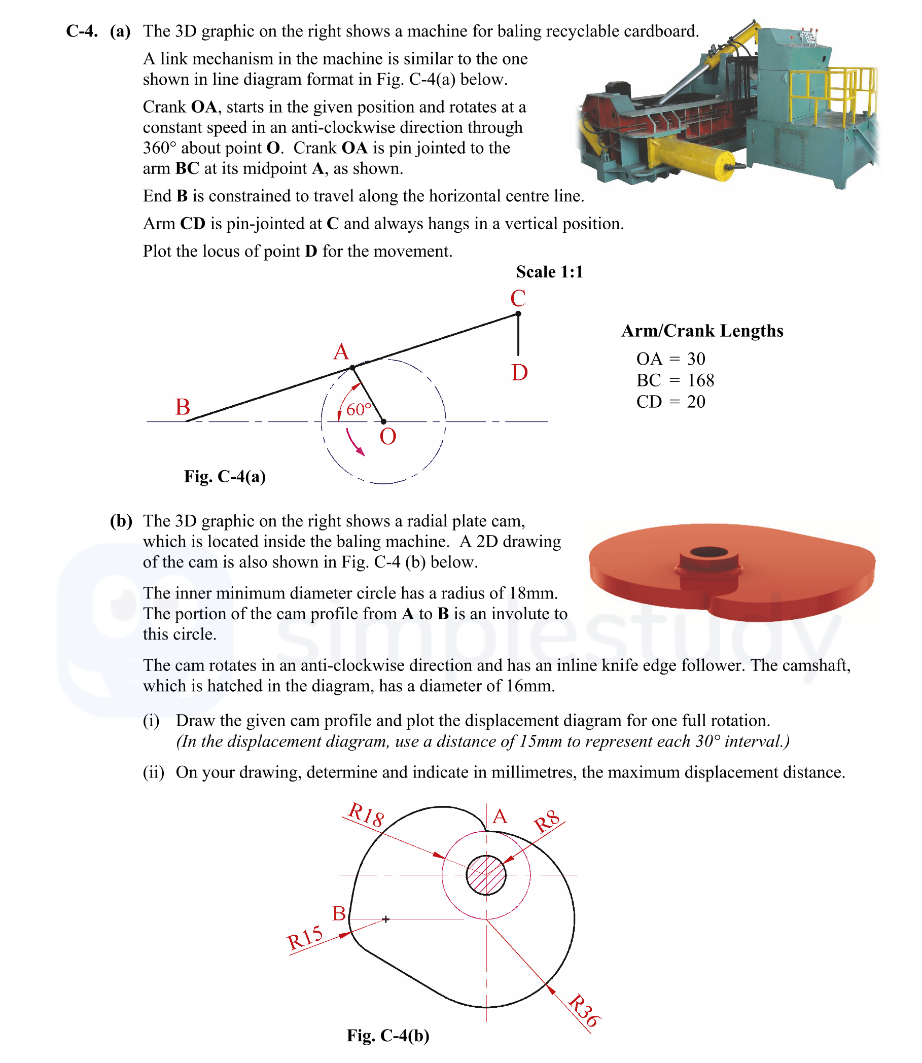
The 3D graphic on the right shows a machine for baling recyclable cardboard.
A link mechanism in the machine is similar to the one shown in the diagram from Fig. C-... show full transcript
Worked Solution & Example Answer:The 3D graphic on the right shows a machine for baling recyclable cardboard - Leaving Cert DCG - Question C-4 - 2013
Step 1
Draw links and circular paths as given.
96%
114 rated
Only available for registered users.
Sign up now to view full answer, or log in if you already have an account!
Answer
Begin by sketching the crank OA, arm BC, and arm CD according to the lengths provided. Ensure that crank OA is 30mm, arm BC is 168mm, and arm CD is 20mm. Orient crank OA at the initial position as described, pointing horizontally to the right from point O.
Step 2
Divide circle into equal parts (min 12).
99%
104 rated
Only available for registered users.
Sign up now to view full answer, or log in if you already have an account!
Answer
Divide the circle for motion indications into at least 12 equal sections. This can be done by marking points at every 30° interval around the circle, allowing for clear visualization of the crank's motion.
Step 3
Locate positions for point B.
96%
101 rated
Only available for registered users.
Sign up now to view full answer, or log in if you already have an account!
Answer
To locate points for B, draw a vertical line from point A at each division marked on the circle, perpendicular to the crank OA. Use the defined length of arm BC (168mm) to mark point B's location for each angle.
Step 4
Locate point C in all positions.
98%
120 rated
Only available for registered users.
Sign up now to view full answer, or log in if you already have an account!
Answer
For point C, draw a vertical line from each position marked for point B downwards a distance of 20mm (length of CD). Mark point C accordingly for each instance as point B moves.
Step 5
Draw arm CD in all positions.
97%
117 rated
Only available for registered users.
Sign up now to view full answer, or log in if you already have an account!
Answer
Connect point C to point D by drawing arm CD vertically from each position of point C. As a result, point D will trace a locus as the crank rotates through the defined angles.
Step 6
Draw the given cam profile and plot the displacement diagram for one full rotation.
97%
121 rated
Only available for registered users.
Sign up now to view full answer, or log in if you already have an account!
Answer
For the cam profile, construct a base circle with a radius of 18mm and draw the involute from point A to point B, ensuring the cam profile accurately reflects the design requirements. For the displacement diagram, plot the movements for one full crank rotation, illustrating the displacement of the follower.
Step 7
Determine and indicate the maximum displacement distance.
96%
114 rated
Only available for registered users.
Sign up now to view full answer, or log in if you already have an account!
Answer
Measure the maximum point on the displacement diagram. The maximum displacement distance should be represented in millimeters, which in this case is taken from the highest point reached on the plot as the crank completes one full rotation. Record this value on the drawing.
Join the Leaving Cert students using SimpleStudy...