C-4. (a) The images on the right show an enlarged view of the piston and crank mechanism from the engine of a jet ski - Leaving Cert DCG - Question C-4 - 2016
Question C-4
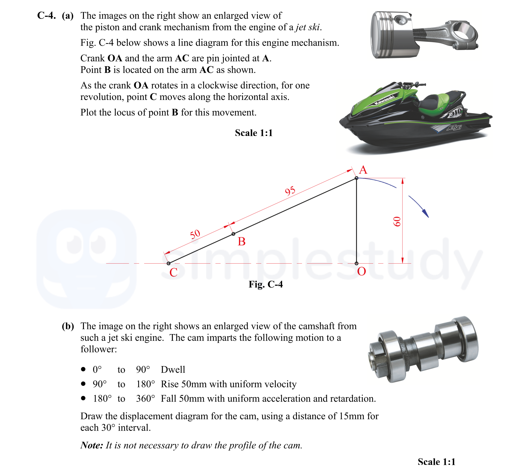
C-4. (a) The images on the right show an enlarged view of the piston and crank mechanism from the engine of a jet ski.
Fig. C-4 below shows a line diagram for this... show full transcript
Worked Solution & Example Answer:C-4. (a) The images on the right show an enlarged view of the piston and crank mechanism from the engine of a jet ski - Leaving Cert DCG - Question C-4 - 2016
Step 1
Set up line diagram (O, A, B & C)
96%
114 rated
Only available for registered users.
Sign up now to view full answer, or log in if you already have an account!
Answer
To begin, draw the line diagram with points O, A, B, and C appropriately positioned. Point O will be the fixed origin, while point A represents the crank pivot. Point C is positioned horizontally to represent the crank movement.
Step 2
Draw circle about O
99%
104 rated
Only available for registered users.
Sign up now to view full answer, or log in if you already have an account!
Answer
Using a compass, draw a circle centered at point O with a radius equal to the length of the crank OA. This circle will represent the path traced out by point A as it rotates.
Step 3
Division of circle
96%
101 rated
Only available for registered users.
Sign up now to view full answer, or log in if you already have an account!
Answer
Divide the circle into equal segments of 30° to effectively plot the positions of points A and subsequently point B. Label each division clearly.
Step 4
Arm AC in rotated positions
98%
120 rated
Only available for registered users.
Sign up now to view full answer, or log in if you already have an account!
Answer
For each 30° increment, draw arm AC extending from point A to its endpoint B. This will illustrate how point B moves as the crank rotates.
Step 5
Points on locus
97%
117 rated
Only available for registered users.
Sign up now to view full answer, or log in if you already have an account!
Answer
Mark the position of point B for each angle as you progress around the circle. Utilize a ruler for accuracy in positioning point B.
Step 6
Draw locus
97%
121 rated
Only available for registered users.
Sign up now to view full answer, or log in if you already have an account!
Answer
Connect the plotted points B with a smooth curve to visualize the path traced by point B during the crank's rotation.
Step 7
Establish follower position at 0°, 90°, 180° and 360°
96%
114 rated
Only available for registered users.
Sign up now to view full answer, or log in if you already have an account!
Answer
Identify and plot the follower's position for the respective angles indicated. At 0°, the follower remains at 50mm height. At 90°, it continues at the same height, then descends as follows.
Step 8
0° to 90° Dwell
99%
104 rated
Only available for registered users.
Sign up now to view full answer, or log in if you already have an account!
Answer
During this period, the follower remains stationary, thus maintaining a height of 50mm throughout this range of motion.
Step 9
90° to 180° Uniform Velocity
96%
101 rated
Only available for registered users.
Sign up now to view full answer, or log in if you already have an account!
Answer
The follower moves uniformly from a height of 50mm to a height of 0mm as the crank moves from 90° to 180°. This descent occurs at a steady rate.
Step 10
180° to 360° Uniform Acceleration and Retardation (UAR)
98%
120 rated
Only available for registered users.
Sign up now to view full answer, or log in if you already have an account!
Answer
During this motion from 180° to 360°, the follower will first accelerate downwards and then decelerate upwards, providing a smooth transition. Draw corresponding angles reflecting this acceleration and deceleration.
Step 11
Complete the Displacement Diagram
97%
117 rated
Only available for registered users.
Sign up now to view full answer, or log in if you already have an account!
Answer
Finalize the displacement diagram by connecting all the plotted points and marking clear height values at the relevant 30° increments. Ensure the diagram is neat and clear for presentation.
Join the Leaving Cert students using SimpleStudy...