Photo AI
The image on the right shows a clamping device used in rock climbing - Leaving Cert DCG - Question C-4 - 2015
Question C-4
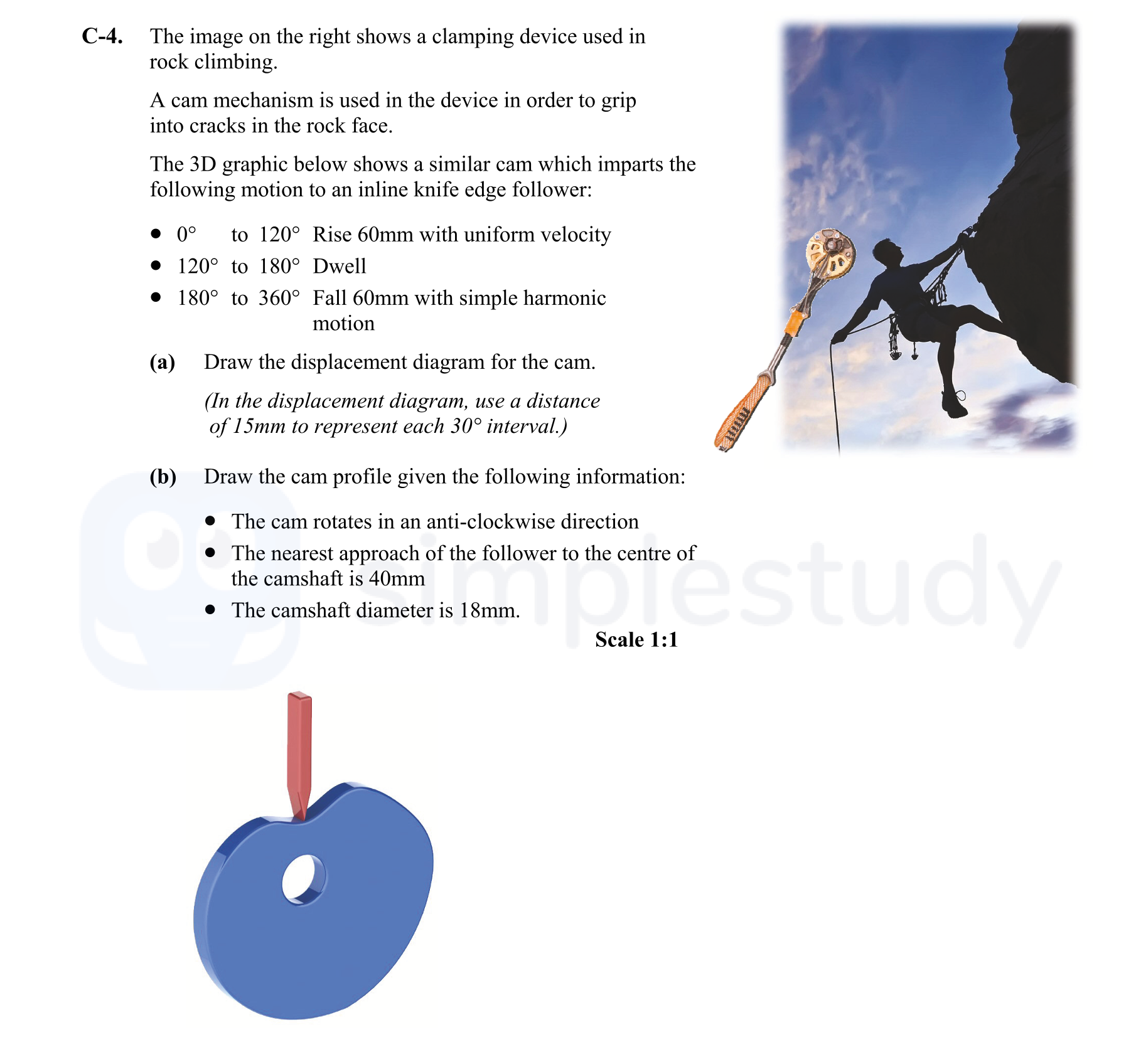
The image on the right shows a clamping device used in rock climbing. A cam mechanism is used in the device in order to grip into cracks in the rock face. The 3D g... show full transcript
Worked Solution & Example Answer:The image on the right shows a clamping device used in rock climbing - Leaving Cert DCG - Question C-4 - 2015
Step 1
Draw the displacement diagram for the cam.

Answer
To draw the displacement diagram for the cam, follow these steps:
-
Establish Angular Divisions: First, divide the circular diagram into 360° sections, ensuring that each segment represents 15mm per 30°.
-
Determine Motion Phases: The motion phases are:
- From 0° to 120° (Rise Phase): The cam rises uniformly 60mm. This means an increase of 60mm across 120°, which gives a gradient of 0.5mm per degree.
- From 120° to 180° (Dwell Phase): The cam remains at a constant height of 60mm, without movement. This section will be horizontal.
- From 180° to 360° (Fall Phase): The cam falls back 60mm with simple harmonic motion (SHM). This phase should be drawn as a curve that represents the SHM descent from 60mm to 0mm.
-
Plot Points: Plot the points at 0°, 120°, 180°, and 360° on the vertical axis according to the heights determined.
-
Connect the Points: Connect the points according to the specified motion, ensuring the rise is a straight line, the dwell is horizontal, and the fall depicts a curve reflecting SHM.
-
Label the Diagram: Finally, label the diagram with the phases: 'Rise', 'Dwell', and 'Fall'.
By following these steps, you will create a correct displacement diagram for the cam.
Step 2
Draw the cam profile.
Answer
To draw the cam profile, follow these steps:
-
Identify Cam Centre and Nearest Approach: Mark the center of the cam, which is fundamental for establishing dimensions. Since the nearest approach to the camshaft is 40mm, start by determining this distance from the center.
-
Draw the Camshaft: Since the camshaft diameter is 18mm, draw a circle representing the camshaft. This will have a radius of 9mm (half of the diameter).
-
Angular Divisions: Using the angular divisions from the displacement diagram, draw radial lines that correspond to the motion phases of the cam. This will include sections for rising and falling actions.
-
Define Points on the Profile: Mark distinct points along the circumference of the cam based on the rise and fall heights. For example, reach up to the height of 60mm corresponding to 120° and adjust the curve for smooth transitions.
-
Complete the Profile: Connect these points smoothly to represent the profile of the cam, ensuring that the design reflects both the rise and fall accurately.
-
Presentation: Finally, ensure the drawing is neat and clearly labeled, including a direction of rotation to clarify the cam's movement.
This structured approach will guide you in creating an accurate cam profile.