Photo AI
The 3D graphic on the right shows an arrangement of playground equipment consisting of an entrance tunnel leading to a play area, which is square in plan - Leaving Cert DCG - Question B-2 - 2011
Question B-2
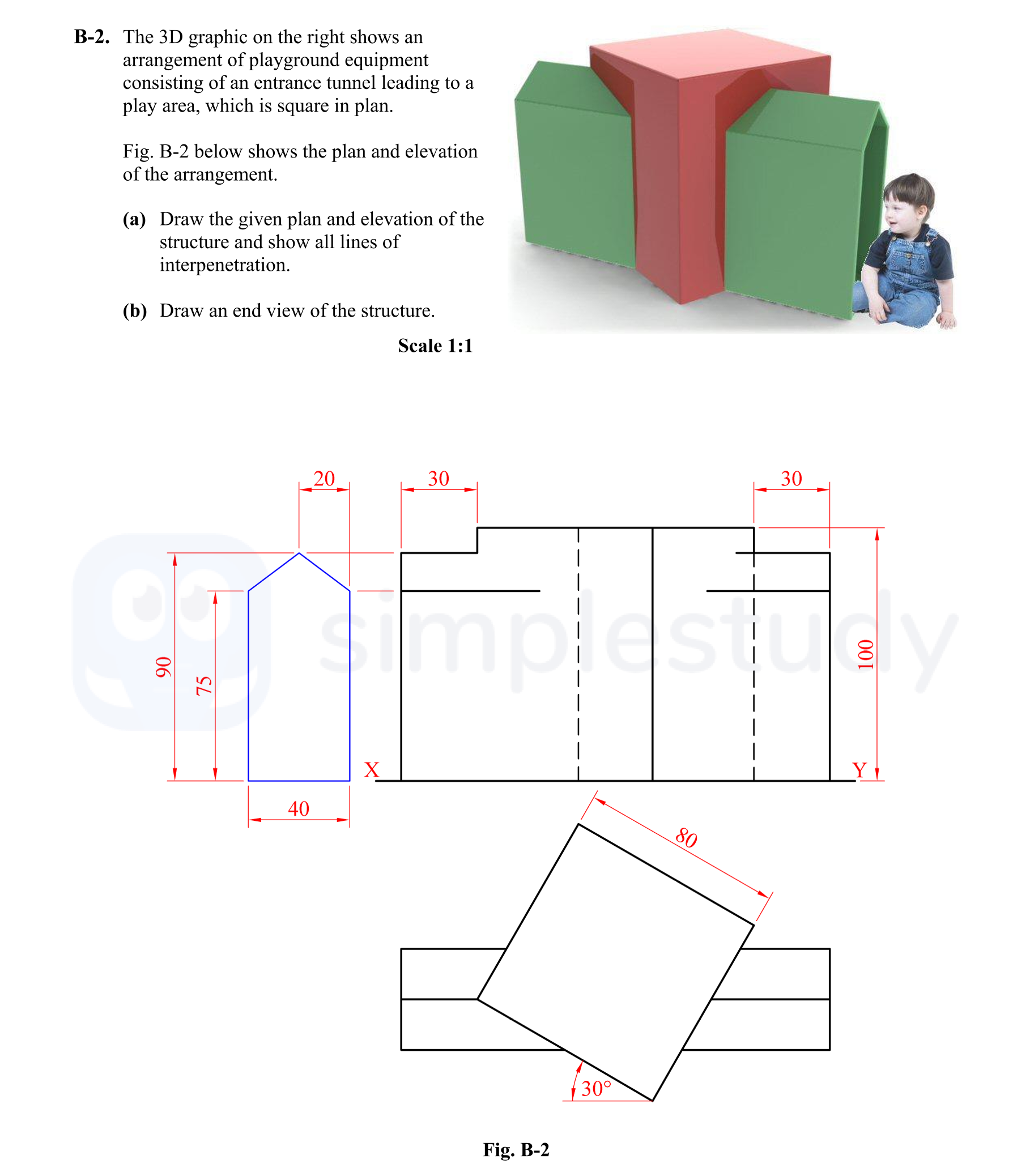
The 3D graphic on the right shows an arrangement of playground equipment consisting of an entrance tunnel leading to a play area, which is square in plan. Fig. B-2 ... show full transcript
Worked Solution & Example Answer:The 3D graphic on the right shows an arrangement of playground equipment consisting of an entrance tunnel leading to a play area, which is square in plan - Leaving Cert DCG - Question B-2 - 2011
Step 1
Draw the given plan and elevation of the structure and show all lines of interpretation.

Answer
Plan of Square Prism
Start by drawing the plan of the square prism. It should be represented as a square (40mm x 40mm) at the bottom left corner of the drawing area.
Elevation of Square Prism
Next, create the elevation view. This view should depict the square prism as a rectangle (40mm width x 75mm height) above the plan.
Include any lines of interpretation to clarify dimensions and features.
Outline Elevation of Tunnel
After that, illustrate the outline elevation of the tunnel to connect with the previous structures, ensuring to depict its arc shape appropriately.
Plan of Tunnel
The tunnel itself should be drawn in the plan view, showing its proportions and connections to the square prism.
Left Hand Side (LHS) Projections
From the left-hand side, project the necessary features from the plan onto the elevation to help visualize the structure.
Locating Points on LHS of Elevation
Clearly mark the points on the left-hand side elevation that correspond to the edges and features defined in the plan.
Complete LHS of Elevation
Ensure the elevation is complete with all details included, representing the structure accurately from the left perspective.
Right Hand Side (RHS) Projections
For the right-hand side, project features from the plan onto the RHS elevation as done with LHS.
Locating Points on RHS of Elevation
Mark the relevant points on the RHS elevation, ensuring they align correctly with the features shown in the plan.
Complete RHS of Elevation
Finalizes the RHS elevation with all necessary details.
Hidden Detail
If applicable, any hidden details should be indicated for a comprehensive understanding of the structure.
Step 2
Draw an end view of the structure.
Answer
Transfer of Widths from Plan
Begin by transferring the widths of the structures shown in the plan directly onto the end view layout. Make sure these widths are accurately represented to maintain scale.
Projection of Heights from Elevation
Next, project the heights from the elevation to align correctly with the widths. Be precise with your vertical measurements.
End View of Square Prism
Draw the end view of the square prism based on transferred widths and projected heights. This should accurately represent the dimensions of the prism.
End View of Tunnel
Lastly, create the end view of the tunnel, showing its curve and overall structure based on the widths and heights previously established.
Ensure that all elements are aligned neatly and presented clearly for readability.