Photo AI
The image shows a cardboard carry-box for a child’s novelty toy - Leaving Cert DCG - Question B-2 - 2018
Question B-2
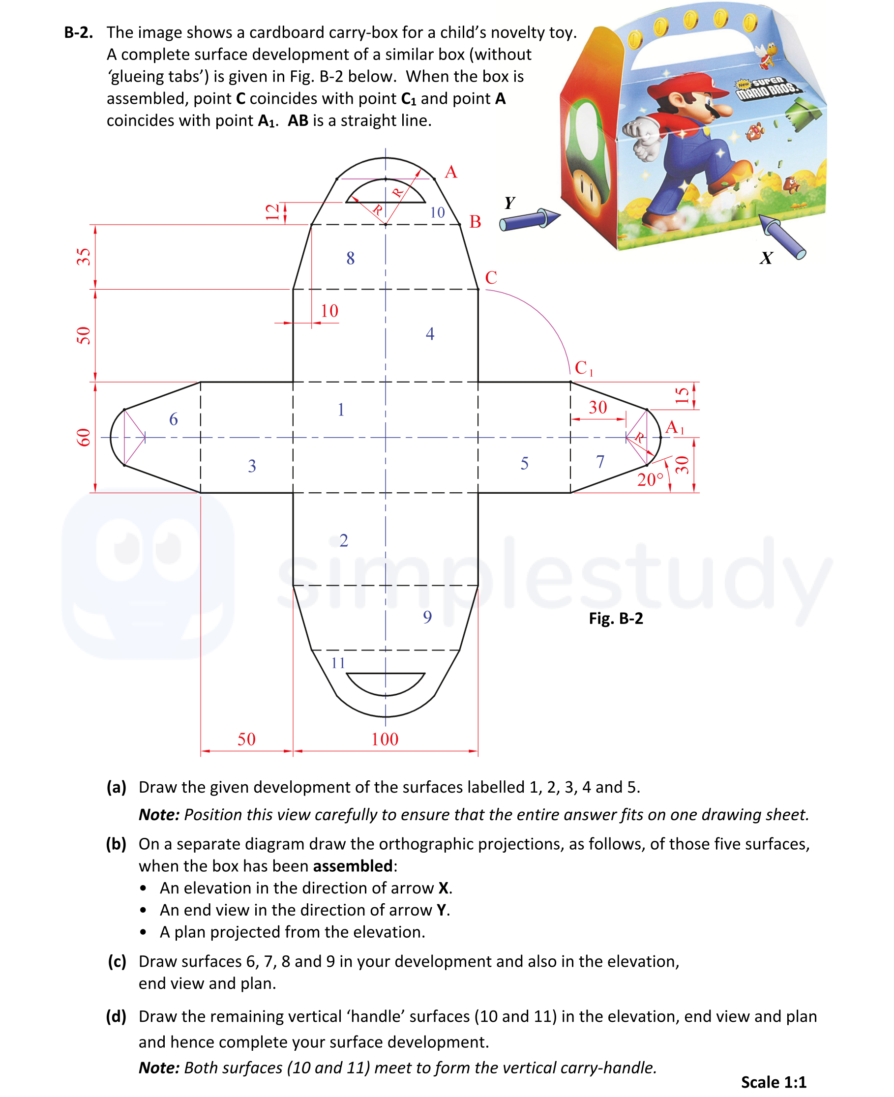
The image shows a cardboard carry-box for a child’s novelty toy. A complete surface development of a similar box (without ‘gluing tabs’) is given in Fig. B-2 below. ... show full transcript
Worked Solution & Example Answer:The image shows a cardboard carry-box for a child’s novelty toy - Leaving Cert DCG - Question B-2 - 2018
Step 1
Draw the given development of the surfaces labelled 1, 2, 3, 4 and 5.

Answer
To draw the development of surfaces labelled 1 to 5, start by creating a flat layout that accurately represents the dimensions given in the diagram. Use a 1:1 scale, ensuring that all surfaces connect where they should. Carefully refer to the provided figure to match the placements of point A, B, C, and any contours accurately in the drawing. Include all necessary lines and curves as specified in the guide.
Step 2
On a separate diagram draw the orthographic projections of those five surfaces.
Answer
For the orthographic projections:
-
Elevation in the direction of arrow X: Draw the front view of the assembled box, ensuring to represent heights accurately. Show all relevant surfaces as they appear when viewed from this direction.
-
Plan projected from the elevation: Represent the top view of the box in its assembled form. Align the view based on the previously drawn elevation, ensuring all edges and parts correspond appropriately.
Step 3
Draw surfaces 6, 7, 8 and 9 in development and orthographic views.
Answer
To illustrate surfaces 6 through 9, begin with their development view based on the dimensional guidance. Each surface should be linked appropriately within the developed surface layout. Follow up with their orthographic representations:
- Surface 6 & 7: Ensure they are drawn in development and displayed accurately in elevation and plan views.
- Surface 8 & 9: Similarly, complete these surfaces with proper curvature and connections, maintaining consistent dimensions throughout.
Step 4
Draw the remaining vertical ‘handle’ surfaces (10 and 11) in the elevation, end view and plan.
Answer
For surfaces 10 and 11, start by outlining the respective curves in the elevation. Ensure both surfaces are accurately proportioned and connected to create a smooth transition between them. Next, draw these surfaces in the end view and plan, verifying that they align with the previously established dimensions for the handle. Finally, ensure that the complete development view includes hidden lines and critical details for clarity.