The graphic below shows a number of sloping arms which support lights in a modern sculpture - Leaving Cert DCG - Question A-3 - 2011
Question A-3
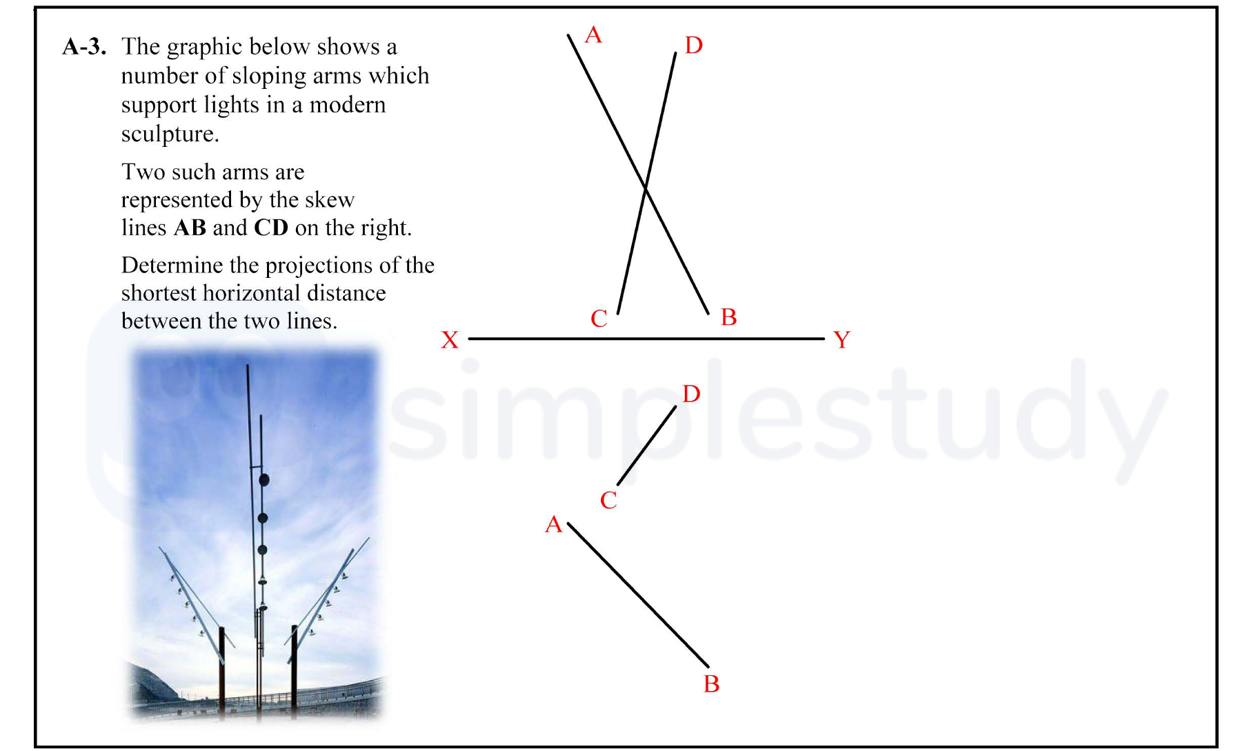
The graphic below shows a number of sloping arms which support lights in a modern sculpture.
Two such arms are represented by the skew lines AB and CD on the right.... show full transcript
Worked Solution & Example Answer:The graphic below shows a number of sloping arms which support lights in a modern sculpture - Leaving Cert DCG - Question A-3 - 2011
Step 1
Creating a plane containing AB (or CD) and parallel to CD (or AB)
96%
114 rated
Only available for registered users.
Sign up now to view full answer, or log in if you already have an account!
Answer
To create the required plane, start from point A and draw a line to point B. This line should be drawn in a way that it remains parallel to the line CD. Ensure that both lines are represented in the same plane for accurate projections.
Step 2
Elevation and plan of horizontal line on parallel plane
99%
104 rated
Only available for registered users.
Sign up now to view full answer, or log in if you already have an account!
Answer
Next, you will need to create the elevation and plan of the line on the newly established parallel plane. This involves projecting points A and B vertically down to the horizontal plane and then connecting the dots to illustrate the horizontal line.
Step 3
X, Y perpendicular to plan of horizontal line
96%
101 rated
Only available for registered users.
Sign up now to view full answer, or log in if you already have an account!
Answer
Establish X and Y axes perpendicular to the plan of the horizontal line to facilitate the projection of points A and B onto these axes.
Step 4
Projections of lines in 1st auxiliary elevation ... (parallel)
98%
120 rated
Only available for registered users.
Sign up now to view full answer, or log in if you already have an account!
Answer
For the projections, draw the first auxiliary projection of lines AB and CD. This involves projecting these lines both above and below the baseline, maintaining their angular relationships.
Step 5
X, Y perpendicular to XY1
97%
117 rated
Only available for registered users.
Sign up now to view full answer, or log in if you already have an account!
Answer
Ensure that a new XY1 line is drawn on the elevations with X and Y points being perpendicular to this line, which helps achieve accurate positioning of the projected lines.
Step 6
Identification of shortest horizontal distance in 2nd auxiliary
97%
121 rated
Only available for registered users.
Sign up now to view full answer, or log in if you already have an account!
Answer
In the second auxiliary view, analyze the created projections to identify the shortest horizontal distance between line segments AB and CD. Use geometric measurement to find and mark this distance.
Step 7
Draw required projections (projecting or measuring to plan and elevation)
96%
114 rated
Only available for registered users.
Sign up now to view full answer, or log in if you already have an account!
Answer
Finally, draw the required projections that represent the measurements to both the plan and elevation. This should include all significant points and lines, ensuring clarity and accuracy in representation.
Join the Leaving Cert students using SimpleStudy...