Photo AI
The graphic below shows a bowling ball and pins - Leaving Cert DCG - Question A-2 - 2013
Question A-2
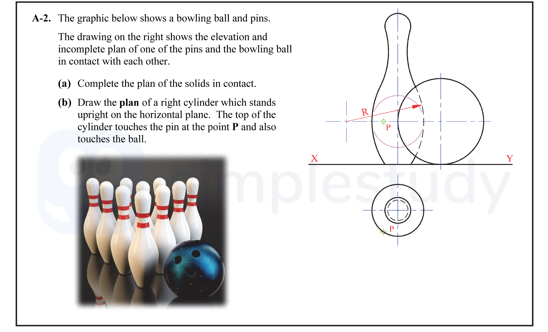
The graphic below shows a bowling ball and pins. The drawing on the right shows the elevation and incomplete plan of one of the pins and the bowling ball in contact... show full transcript
Worked Solution & Example Answer:The graphic below shows a bowling ball and pins - Leaving Cert DCG - Question A-2 - 2013
Step 1
Complete the plan of the solids in contact.

Answer
-
Location of the Sphere's Center: Identify the center of the sphere in elevation, which is tangential to the pin. It should be located directly above the pin at the given heights.
-
Projection to Correct Point in Plan: Project the identified center from elevation directly down to the plan view. This provides the correct point on the horizontal plane.
-
Rotation About Center in Plan: Rotate the sphere's center around the pin in the plan view. This demonstrates the sphere's influence over the pin's position.
-
Location of Required Center in Plan: Mark the required center point, which should be indicated as (1,1) considering the context of the diagram.
-
Draw Required Plan of Sphere: Draw the complete circular outline of the sphere tangentially touching the pin within the plan view.
Step 2
Draw the plan of a right cylinder which stands upright on the horizontal plane.
Answer
-
Draw Line from Center of Pin Through P in Plan: Start by drawing a vertical line from the center of the pin straight through point P which indicates where the cylinder will be placed.
-
Draw 2 Sets of Corresponding Arcs/Lines: From point P and the pin's center, create two arcs that represent the top of the cylinder and its base. These should be symmetrical around the center line.
-
Draw Locus to Determine Required Center: Find the locus formed by the top of the cylinder touching the ball. This will help in determining the required center for the cylinder.
-
Draw Required Plan of Cylinder: Finally, encapsulate the arcs with straight lines to define the cylinder in the plan view.