Photo AI
The image on the right shows a beach art structure at a holiday destination - Leaving Cert DCG - Question C-2 - 2022
Question C-2
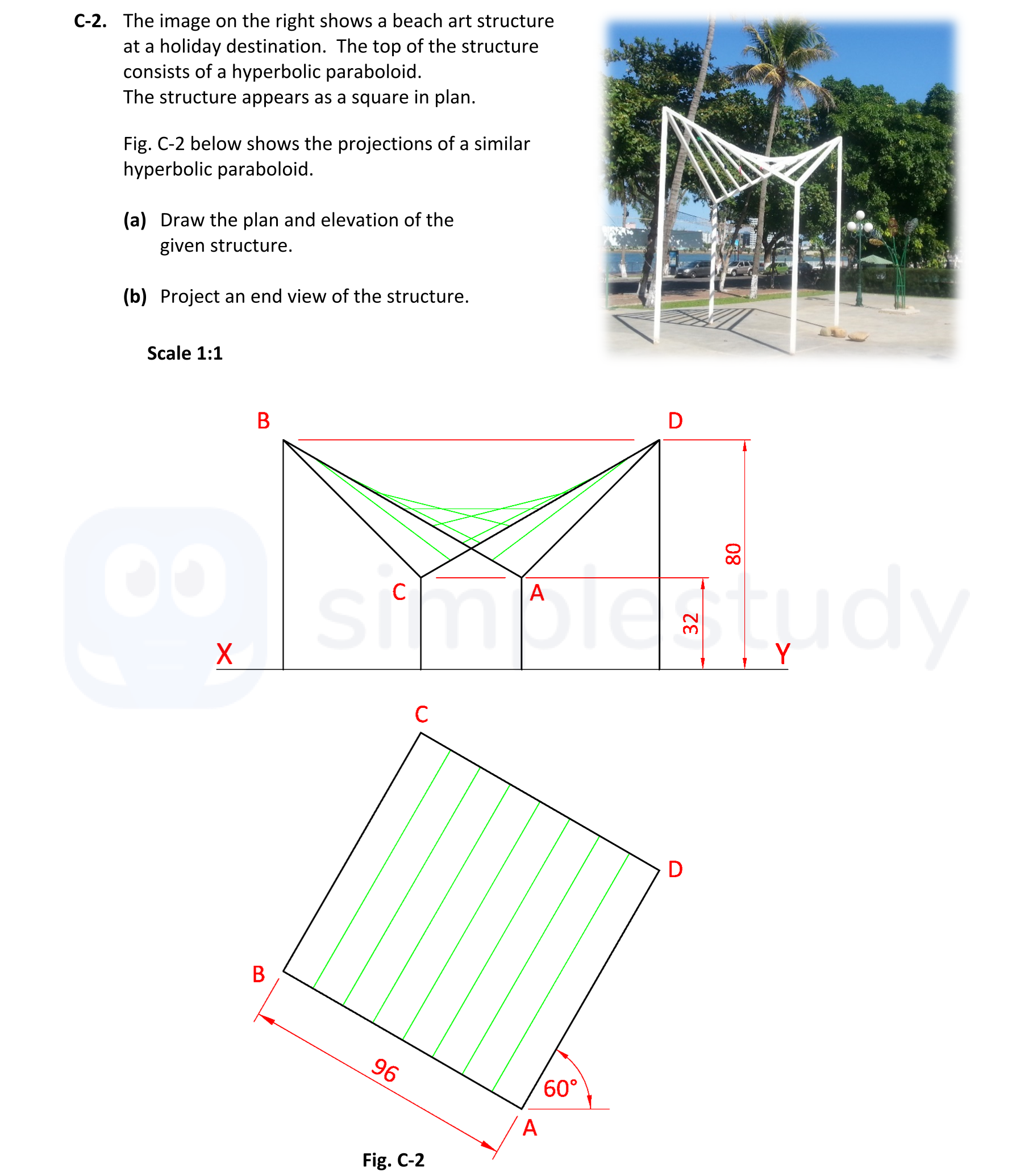
The image on the right shows a beach art structure at a holiday destination. The top of the structure consists of a hyperbolic paraboloid. The structure appears as a... show full transcript
Worked Solution & Example Answer:The image on the right shows a beach art structure at a holiday destination - Leaving Cert DCG - Question C-2 - 2022
Step 1
Draw the plan and elevation of the given structure.

Answer
-
Outline of Surface ABCD in Plan: Begin by drawing a square layout for surface ABCD with each side measuring 96 units, aligned to the axes as shown in Fig. C-2.
-
Elements in Plan (incl. division): Divide the square into equal sections, showing the sectioning for clarity in elevation. Mark the corners as points A, B, C, and D respectively.
-
Outline of Surface in Elevation: Project the outlines of the surfaces from the plan to the elevation view. The elevation will depict a downward curve from points B and D to point C, showcasing the hyperbolic shape.
-
Elements in Elevation (incl. division): Divide the elevation into divisions aligning with the horizontal and vertical edges, denoting the slopes. Label corresponding heights according to the plan dimensions.
-
Completion of Elevation (vertical legs): Finally, ensure to denote the vertical supports represented in the elevation by drawing vertical lines from points A, C to the base line.
Step 2
Project an end view of the structure.
Answer
-
Determine Heights and Widths for Surface ABCD: Calculate the heights at points A (32 units) and B (80 units) to understand the end view projection.
-
Draw the Outline of Hyperbolic Paraboloid Surface: Create a curved outline representing the hyperbolic surface from the side view, ensuring to incorporate the heights determined in the previous step.
-
Draw Elements: Add in the support structures at points A and B, showing the vertical connections back to the ground as per the elevations.
-
Completion of End View (vertical legs): Include the vertical legs in the end view to highlight structural integrity.
-
Presentation: Ensure that the drawings are neat, labeled, and utilize appropriate line weights to distinguish between different elements.