Photo AI
Distinguish between intrinsic conduction and extrinsic conduction in a semiconductor - Leaving Cert Physics - Question b - 2010
Question b
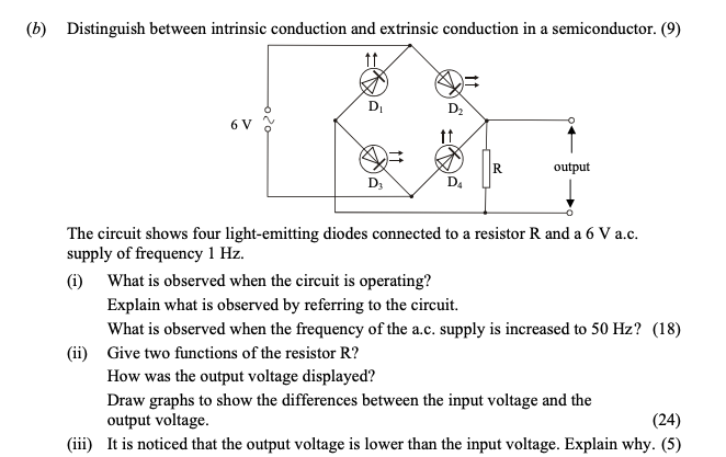
Distinguish between intrinsic conduction and extrinsic conduction in a semiconductor. The circuit shows four light-emitting diodes connected to a resistor R and a 6... show full transcript
Worked Solution & Example Answer:Distinguish between intrinsic conduction and extrinsic conduction in a semiconductor - Leaving Cert Physics - Question b - 2010
Step 1
What is observed when the circuit is operating?

Answer
During one second cycle, the following observations can be made:
- D1 and D2 flash together during one half cycle, creating a bright effect.
- D3 and D4 then flash, creating a visual distinction (flashing) on the output.
In more detail, D1 and D2 are forward-biased during one half cycle, allowing current to flow and emit light, while D3 and D4 become forward-biased in the subsequent half cycle. Therefore, the result is a patterned illumination where alternating pairs of LEDs light up.
Step 2
Explain what is observed by referring to the circuit.
Answer
In the circuit, when D1 and D2 are forward-biased, they will conduct, illuminating those two diodes. On the other hand, D3 and D4 are reverse-biased during this time and will not emit light. As the cycle alternates, D3 and D4 become forward-biased, and D1 and D2 turn off, resulting in the flashing behavior of the LEDs:
- D1, D2 emit light during each half cycle, and D3, D4 remain off.
- The same happens in the reverse scenario, creating a continual flashing effect.
Step 3
What is observed when the frequency of the a.c. supply is increased to 50 Hz?
Answer
When the frequency is increased to 50 Hz, LEDs will flash continuously without a noticeable gap. This is because the cycle duration becomes shorter, allowing less time for the diodes to be off, leading to the perception of continuous light rather than isolated flashes.
Step 4
Step 5
Step 6
Draw graphs to show the differences between the input voltage and the output voltage.
Answer
The input voltage is a sinusoidal wave representing the alternating current supply. The output voltage waveform will differ, showing a pattern that reflects the forward-biased operation of the diodes:
- Input Voltage Graph: A smooth sinusoidal wave.
- Output Voltage Graph: A rectified and pulsed output, illustrating the voltage across the LEDs as they turn on and off in sync with the alternating supply. Both graphs should be drawn in-phase for clarity against the timeline.
Step 7
It is noticed that the output voltage is lower than the input voltage. Explain why.
Answer
The reduction in output voltage compared to input is primarily due to the voltage drop across each LED, which typically ranges around 1.6V. Additionally, some voltage is converted to heat within the diodes due to their electrical resistance and various junction losses, resulting in an overall lower output voltage.