Wave-Like Properties of Light (VCE SSCE Physics): Revision Notes
Wave-Like Properties of Light
Introduction to electromagnetic waves
Light is a type of electromagnetic wave - a transverse wave consisting of perpendicular oscillating electric and magnetic fields. This understanding emerged from James Clerk Maxwell's pioneering work in 1826, when he demonstrated mathematically that the laws of electricity and magnetism predicted the existence of electromagnetic waves.
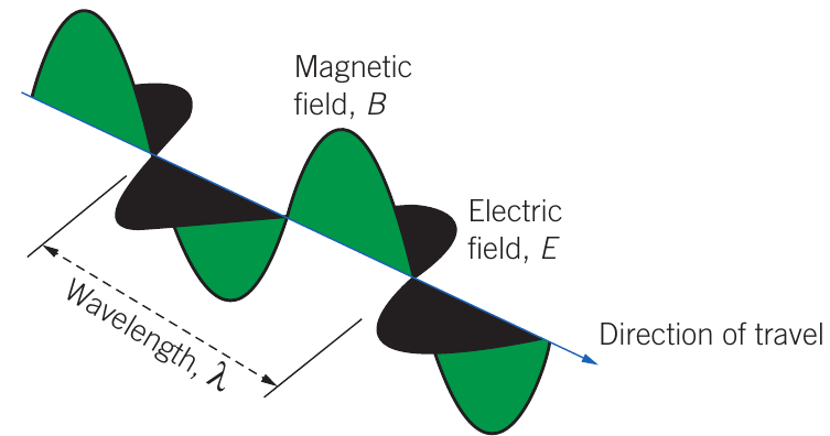
In an electromagnetic wave, the electric field and magnetic field oscillate perpendicular to each other and to the direction of travel, forming a transverse wave. All electromagnetic waves travel at the speed of light, , in a vacuum.
Key properties:
- Electric and magnetic fields oscillate at right angles to each other
- Both fields are perpendicular to the direction of wave travel
- Speed in vacuum:
- Wavelengths range from to more than
The wave equation
The relationship between speed, frequency, and wavelength for electromagnetic waves is given by:
Where:
- = speed of light in vacuum ()
- = frequency (Hz)
- = wavelength (m)
When electromagnetic waves travel through a medium (such as glass or water), they move more slowly than in a vacuum. The relationship is:
Where:
- = speed of light in the medium (m·s⁻¹)
- = refractive index of the medium
- = speed of light in vacuum
The refractive index is a measure of how much slower light travels through a material compared to a vacuum. Materials with higher refractive indices slow light down more significantly.
Worked Example: Calculating Wavelength
A radio station broadcasts at a frequency of 95.5 MHz. What is the wavelength of these radio waves?
Step 1: Identify the known values
Step 2: Use the wave equation
Rearranging:
Step 3: Substitute and calculate
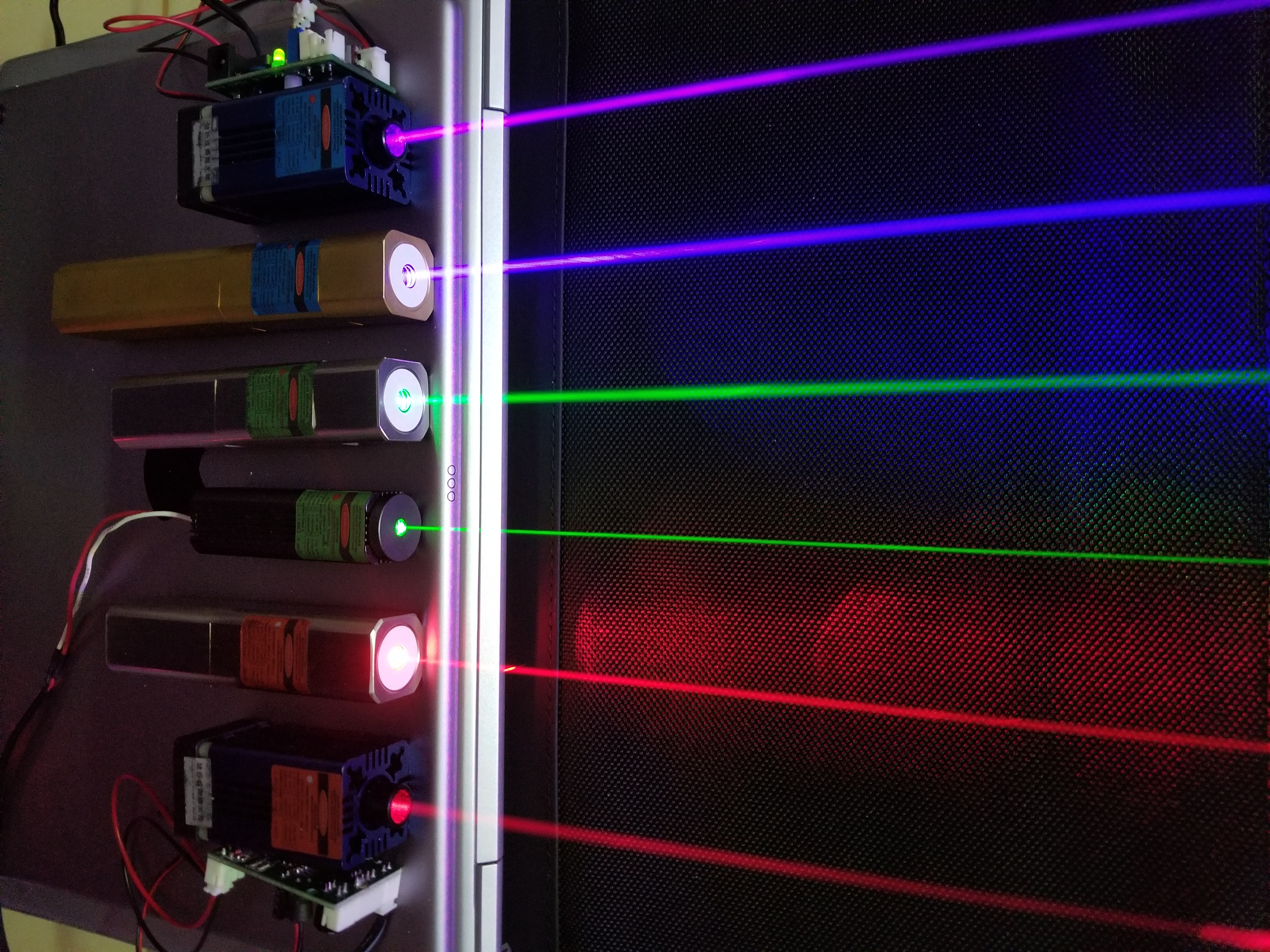
Applications of lasers
Lasers are a key technology demonstrating light's properties with numerous applications across multiple fields:
- Medicine: retinal repair, laser scalpels (incisions as narrow as m), dental procedures
- Measurement: distance measurement, surveying, Earth-Moon distance monitoring (accurate to 15 cm)
- Industry: cutting and welding in engineering and garment construction
- Communications: optical fibres using infrared laser light
- Technology: DVD readers, barcode scanners, 3D scanning, LIDAR mapping
- Research: LIGO detectors for gravitational waves
- Agriculture: autonomous weeding systems
Standing waves
A standing wave (also called a stationary wave) is a wave pattern that oscillates in time but whose amplitude profile does not move in space. Standing waves form when two equal waves travelling in opposite directions meet and overlap.
Formation of standing waves
Standing waves can be produced in a stretched string by fixing one end and vibrating the other end. The reflected wave overlaps with the original wave, and when the frequency meets certain conditions, a standing wave pattern emerges.
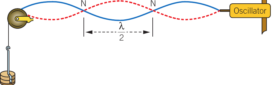
The key features of a standing wave are:
- Nodes (N): points of minimal oscillation where the displacement is always zero
- Antinodes (A): points of maximum oscillation, located midway between nodes
- The wave shape does not travel left or right; instead, every point oscillates vertically
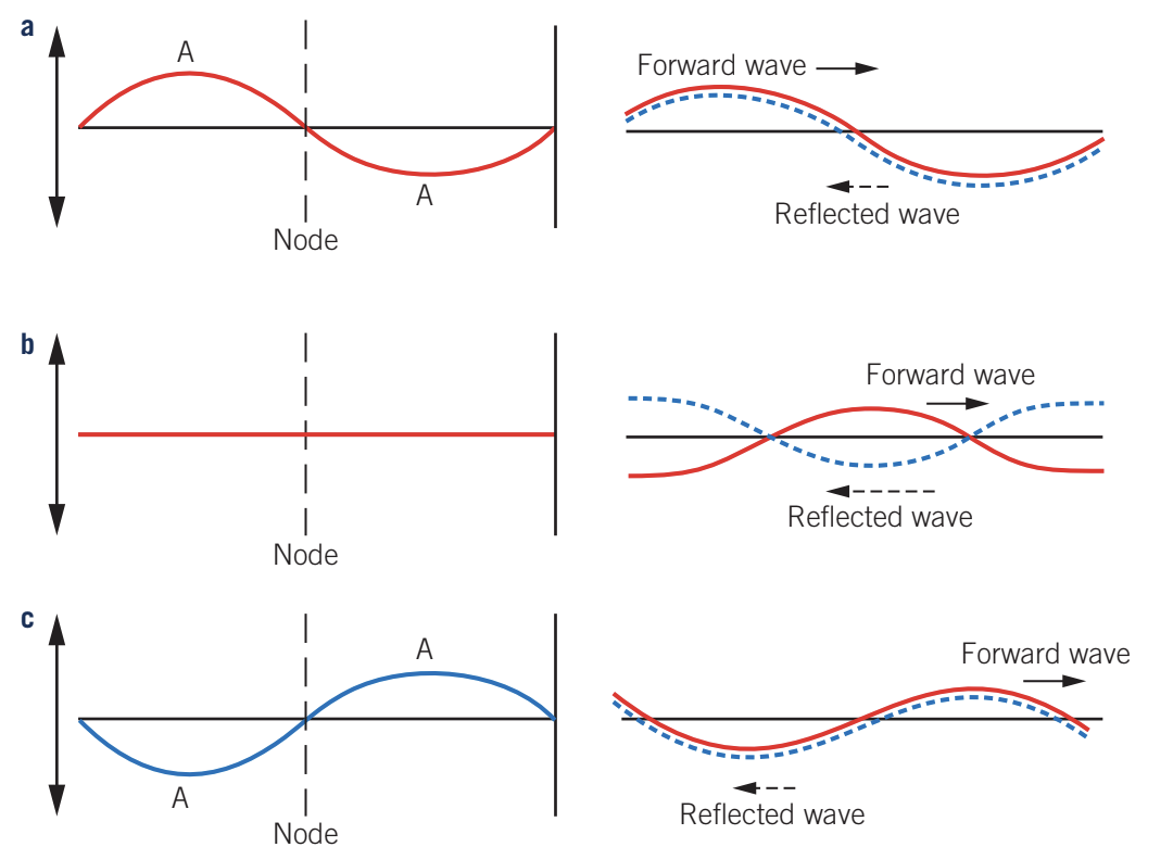
Formation through superposition
Standing waves result from the principle of superposition - when two or more waves overlap, their displacements add together. The diagrams show how forward and reflected waves combine at different times:
Position a: The incident and reflected waves are in phase, producing maximum displacement (constructive interference).
Position b: The waves are out of phase, cancelling each other to produce no displacement (destructive interference).
Position c: The waves again reinforce, producing maximum displacement in the opposite direction.
Conditions for standing waves with nodes at both ends
For a standing wave to form with nodes at both ends:
- The length of the string must equal a whole number of half wavelengths:
- Nodes are regularly spaced at intervals of
- Antinodes are also spaced at intervals of , positioned midway between nodes
This principle applies to both transverse waves (like waves on a string) and longitudinal waves (like sound waves in a pipe open at both ends).
Harmonic series
When standing waves form in a stretched string, they create a series of patterns called the harmonic series. Each harmonic has its own frequency:
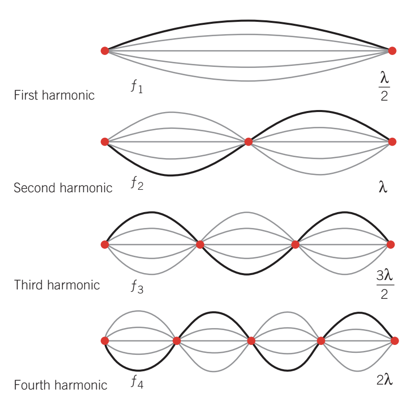
The first harmonic (or fundamental) is the simplest pattern, where the string length equals half a wavelength:
The frequency of the fundamental is:
For the second harmonic, the string length equals one full wavelength:
The general equation for the th harmonic is:
Where:
- = an integer (1, 2, 3, ...)
- = speed of the wave (m·s⁻¹)
- = length of the string (m)
This means each harmonic frequency is a whole number multiple of the fundamental frequency.
Worked Example: Calculating Harmonic Frequencies
A guitar string of length 0.65 m has a wave speed of 400 m·s⁻¹. Calculate the frequencies of the first three harmonics.
Step 1: Calculate the fundamental frequency
Step 2: Calculate the second harmonic
Step 3: Calculate the third harmonic
Standing light waves
Standing waves can also form with light. Inside a laser cavity, light reflects between mirrors and can establish a standing wave pattern:
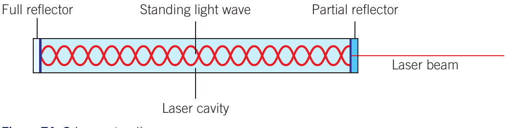
The laser cavity contains:
- A full reflector at one end
- A partial reflector at the other end (allowing some light to escape as the laser beam)
- Standing light waves between the mirrors
Diffraction
Diffraction is the spreading of a wave when it passes through a narrow opening or around an obstacle. While easily observed with sound and water waves, diffraction also occurs with light, though it can be harder to see.
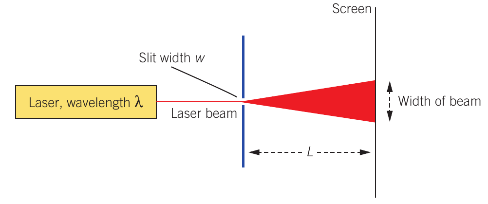
When a laser beam passes through a narrow slit, it spreads out. The amount of spreading depends on:
- The wavelength of light ()
- The width of the slit ()
- The distance to the screen ()
The width of the diffracted beam on the screen is proportional to .
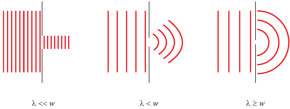
Effect of slit width on diffraction
The relationship between wavelength and slit width determines the extent of diffraction:
When (wavelength much smaller than slit width):
- Minimal diffraction occurs
- Light travels almost in straight lines
- Geometric propagation dominates
When (wavelength smaller than slit width):
- Moderate diffraction occurs
- Light spreads noticeably
When (wavelength equal to or greater than slit width):
- Significant diffraction occurs
- The slit behaves like a point source
- Light spreads through 180°
As a rough guide, when , the beam spreads at about 1°.
Intensity distribution
Diffraction patterns can be represented as graphs showing light intensity versus position on the screen:
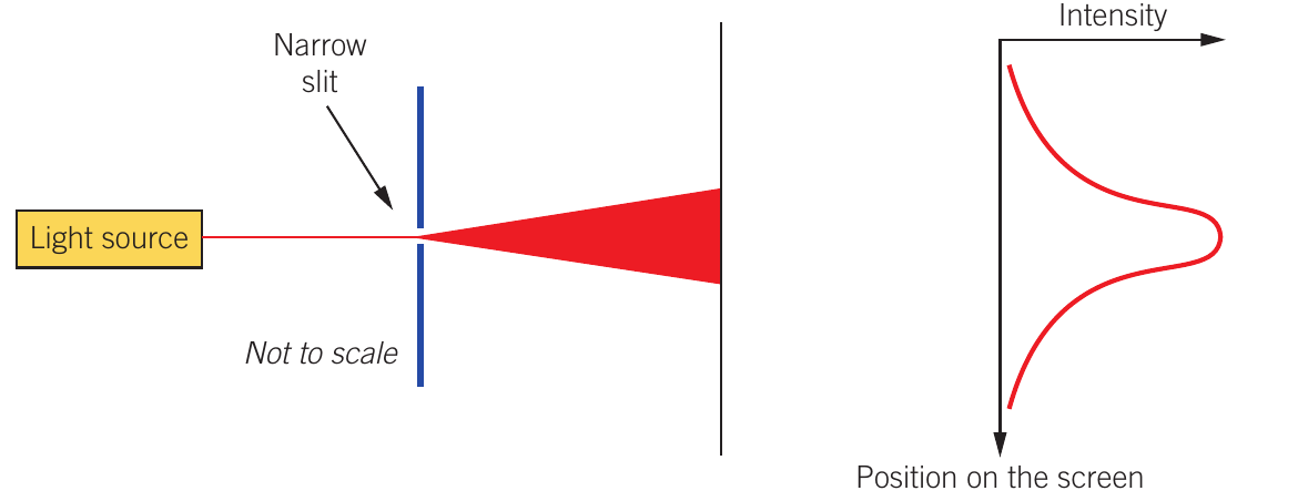
The pattern shows:
- A bright central maximum
- Weaker side lobes on either side
- Dark regions between the bright areas
Diffraction around obstacles
Diffraction also occurs when waves encounter obstacles:
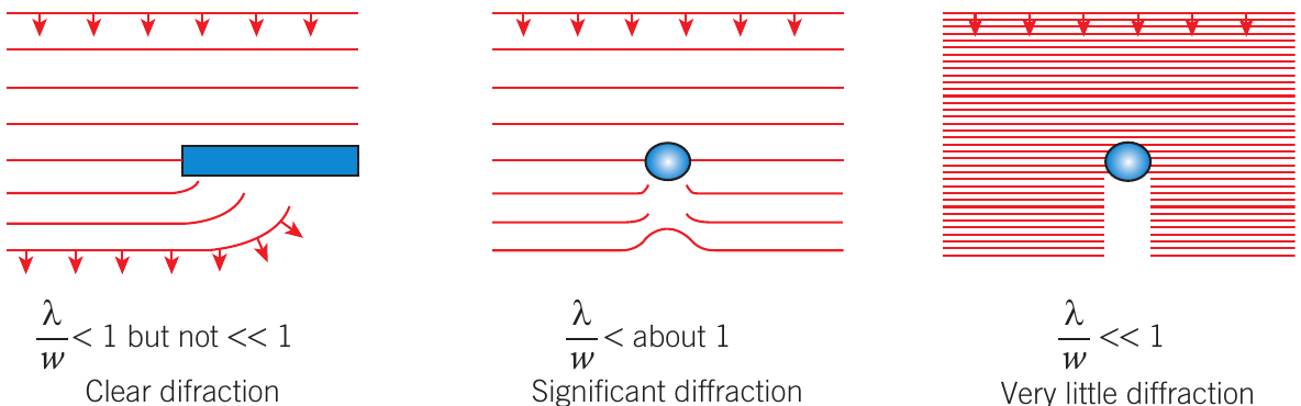
The amount of diffraction around an obstacle depends on the ratio (where is the obstacle width):
- When but not : clear diffraction occurs
- When : significant diffraction occurs
- When : very little diffraction occurs
Applications to resolving close objects
Diffraction limits our ability to distinguish between two close light sources. Consider viewing car headlights at different distances:
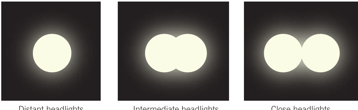
Distant headlights: The diffracted images overlap completely, appearing as a single light source.
Intermediate distance: The images begin to separate but still overlap partially.
Close headlights: The images are clearly separated and distinguishable as two distinct sources.
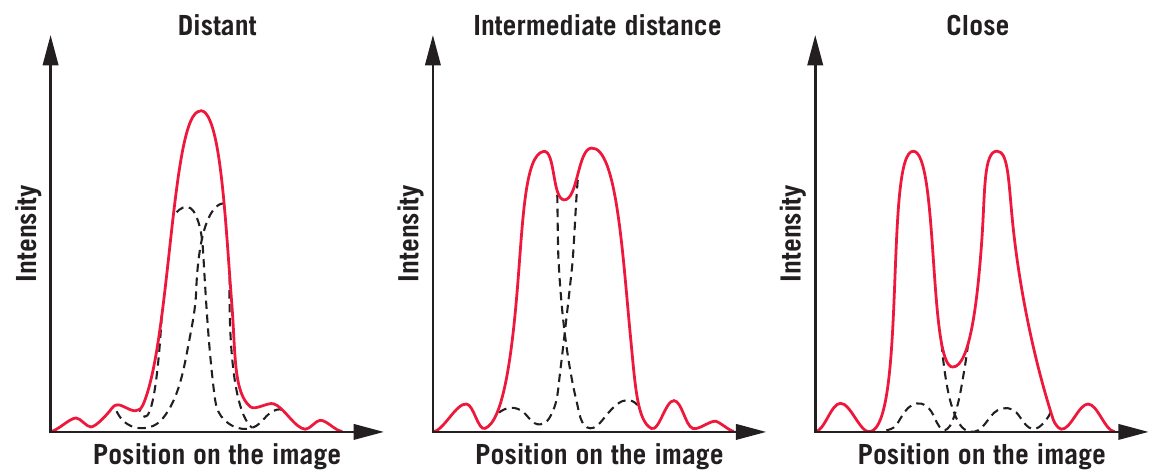
This limitation affects all optical systems, including telescopes and the human eye. The diffraction patterns can be represented graphically, showing how the intensity peaks separate as the sources get closer.
Diffraction and astronomical telescopes
Diffraction affects all telescopes, including space telescopes like the Hubble and James Webb telescopes:
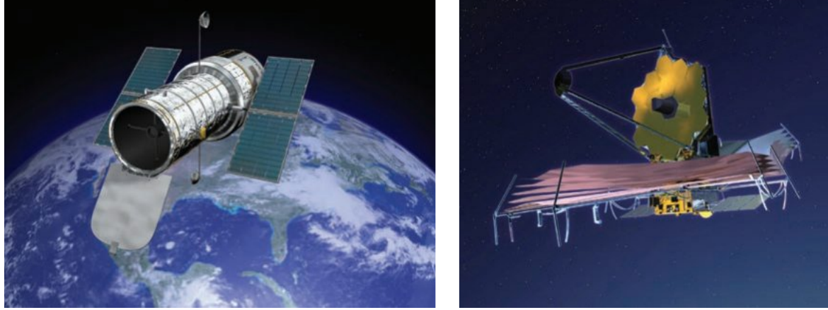
The ability to separate close astronomical objects depends on the ratio, where is the telescope aperture (diameter). To reduce diffraction effects:
Increase aperture size: Larger telescopes have smaller diffraction. Many terrestrial reflecting telescopes have diameters greater than 10 m.
Use shorter wavelengths: Observing in ultraviolet rather than visible light reduces diffraction.
Examples:
- Hubble Space Telescope: aperture of 2.4 m, observes in ultraviolet and visible light
- James Webb Space Telescope: aperture of 6.5 m, observes in infrared and visible light
Space telescopes avoid the additional problem of atmospheric turbulence, which causes stars to twinkle and distorts images from ground-based telescopes.
Alpha Crucis example: The bottom star of the Southern Cross, Alpha Crucis, is actually a double star. A small telescope can resolve the two stars, but the naked eye (with pupil diameter about 5 mm) sees only a single star because the diffracted images overlap.
Huygens' principle
More than a century before the wave model was established, scientist Christiaan Huygens proposed a principle for light propagation. He suggested that every point on a light wavefront acts as a source of secondary wavelets (wave-like phenomena that begin with zero amplitude). The envelope of all these wavelets forms the new wavefront.
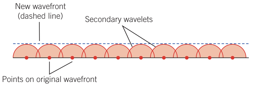
For a plane wavefront:
- Points on the original wavefront each generate secondary wavelets
- The tangent line to these wavelets forms the new wavefront
- The wavefront propagates forward
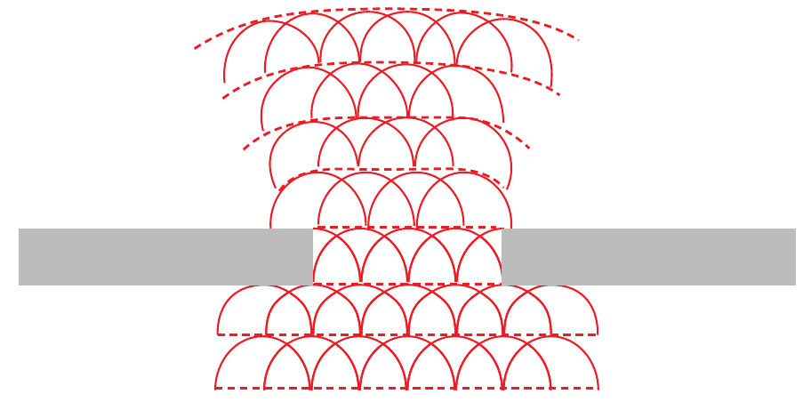
When a plane wavefront reaches an opening:
- Wavelets spread from all points in the opening
- The wavefront spreads or diffracts
- This explains the spreading of light through apertures
The Poisson spot
A remarkable demonstration of diffraction is the Poisson spot - a bright spot appearing at the centre of the shadow cast by a circular object:
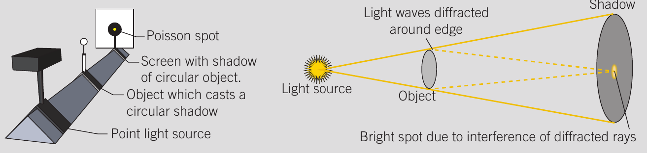
Explanation: Light diffracts around the edges of the circular object. Since all points on the edge are equidistant from the centre of the shadow, the diffracted wavefronts arrive at the centre simultaneously and in phase. This creates constructive interference, producing a bright spot.
The Poisson spot is named after Siméon Denis Poisson, who believed light was particle-like and thought such a bright spot in a shadow should be impossible. Ironically, when the spot was demonstrated by François Arago, it became clear evidence for light's wave-like behaviour.
Young's double slit experiment
At the start of the 19th century, debate about the nature of light was dominated by Isaac Newton's particle theory. Newton believed light consisted of coloured particles called "corpuscles" that travelled in straight lines at great speed. This theory could explain reflection, refraction, and dispersion of white light into colours.
However, Thomas Young's famous double slit experiment established light's wave-like nature and turned the tide of scientific opinion.
Original experiment
In Young's original experiment, he allowed a narrow beam of sunlight to be cut in two by a thin card, creating two light sources:
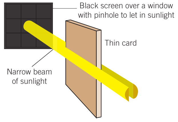
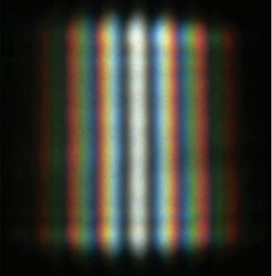
When the light from these two sources overlapped (due to diffraction), a series of dark and bright bands appeared, with the bright fringes edged with colours.
These interference fringes could not be explained by Newton's particle theory - a wave model was necessary.
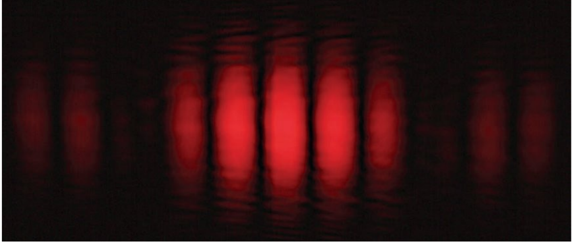
Modern setup
Modern versions typically use a monochromatic laser instead of sunlight, producing a clearer pattern:
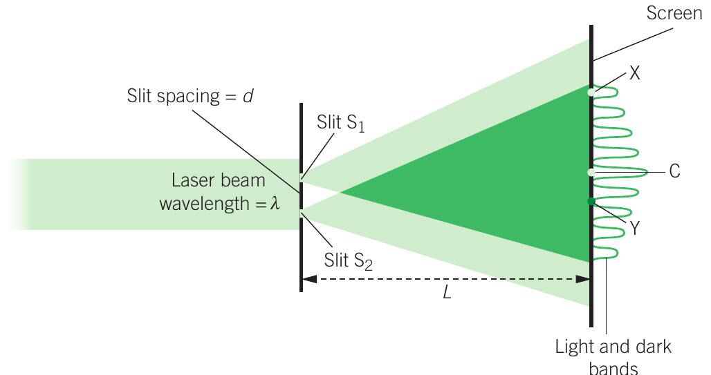
The setup consists of:
- A laser beam with wavelength
- Two parallel slits separated by distance (approximately 0.5 mm)
- A screen at distance (typically several metres away)
- An interference pattern of alternating bright and dark bands
Understanding the interference pattern
At point C (centre):
- Bright band appears
- Light from slits and travels exactly the same distance
- Waves arrive in phase (peaks and troughs matching)
- Constructive interference occurs - the intensities add together
At point X (third bright band):
- The distance exceeds distance by exactly three wavelengths:
- Waves still arrive in phase
- Constructive interference produces a bright band
At point Y (second dark band):
- The path difference is:
- Waves arrive out of phase
- Destructive interference occurs - the waves cancel each other
Conditions for interference
Bright bands (constructive interference): Path difference =
Where
Dark bands (destructive interference): Path difference =
Where
Fringe spacing formula
The distance between adjacent bright (or dark) bands is given by:
Where:
- = distance between bright bands (or dark bands) (m)
- = distance between slits and screen (m)
- = separation between slits (m)
- = wavelength of light (m)
Important: This formula is valid when (the slit separation is much smaller than the distance to the screen).
This formula shows that:
- Increasing wavelength increases fringe spacing
- Increasing distance to screen increases fringe spacing
- Increasing slit separation decreases fringe spacing
Worked Example: Calculating Fringe Spacing
In a double slit experiment, red laser light of wavelength 650 nm passes through two slits separated by 0.40 mm. The screen is placed 2.5 m away. Calculate the fringe spacing.
Step 1: Convert all values to standard units
Step 2: Apply the fringe spacing formula
Step 3: Substitute and calculate
Coherence
For clear interference patterns to appear, the two light sources must be coherent - they must be monochromatic (single wavelength) with a fixed or zero phase difference between them.
Coherent sources:
- Laser light (fully coherent)
- Light from a single source split into two beams
- Two slits illuminated by the same narrow light source
Incoherent sources:
- Two separate incandescent globes
- Two separate LEDs
- Light waves with random phase relationships
Young's original experiment used sunlight passing through a single narrow slit before reaching the double slits. This introduced sufficient coherence to produce visible interference bands. Modern demonstrations typically use lasers, which are fully coherent and produce clearer, brighter patterns.
Evidence for wave-like nature of light
Young's double slit experiment provided compelling evidence for light's wave-like nature by demonstrating that light behaves identically to other established wave phenomena.
Comparison with other waves
The same interference patterns observed with light can be demonstrated with:
Sound waves:

Two loudspeakers producing the same frequency note in phase create regions of:
- Maximum sound intensity (antinodes) where path differences equal whole wavelengths
- Minimum sound intensity (nodes) where path differences equal odd multiples of half wavelengths
Water waves:
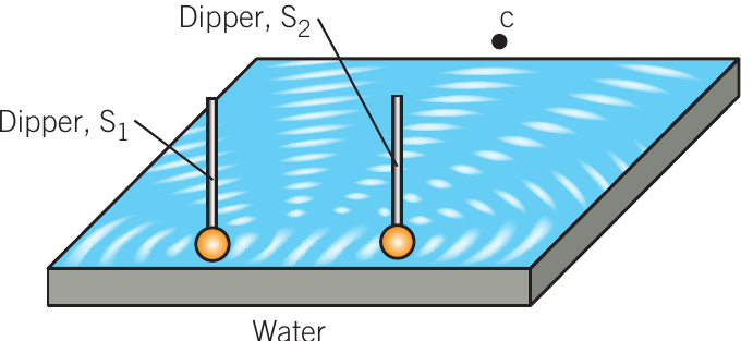
Two dippers in a ripple tank producing circular waves in phase create:
- A central antinode where path difference is zero (constructive interference)
- Alternating nodes and antinodes where path differences vary by half wavelengths
The interference pattern in water is identical to the pattern observed with light, providing clear evidence that light behaves as a wave.
Additional wave-like evidence
Beyond Young's experiment, other observations support light's wave-like nature:
- Diffraction: Light spreads when passing through narrow openings or around obstacles
- Light beams pass through each other without interaction
- Reflection and refraction: Light reflects and refracts according to wave principles
- Polarisation: A property unique to transverse waves
- Dispersion: White light separates into component colours (spectrum)
- Light travels in straight lines (consistent with wave propagation)
The wave model successfully explains all these phenomena, whereas the particle model struggled to account for diffraction, polarisation, and the results of Young's experiment.
Remember!
Key Points to Remember:
-
Electromagnetic waves consist of perpendicular oscillating electric and magnetic fields travelling at in a vacuum, related by .
-
Standing waves form when waves travelling in opposite directions superpose, creating fixed patterns of nodes (zero amplitude) and antinodes (maximum amplitude). For strings fixed at both ends, the length must equal a whole number of half wavelengths.
-
Diffraction is the spreading of waves through openings or around obstacles. The amount depends on the ratio : when wavelength approaches or exceeds the gap/obstacle width, significant diffraction occurs. This limits the resolution of optical instruments.
-
Young's double slit experiment demonstrates light's wave-like nature through interference patterns. Constructive interference (bright bands) occurs when path difference = ; destructive interference (dark bands) occurs when path difference = . The fringe spacing is .
-
Coherent sources (monochromatic with fixed phase relationship) are required for clear interference patterns. This is why lasers produce excellent results in modern demonstrations of wave phenomena.