Circuit boards (AQA GCSE Design and Technology): Revision Notes
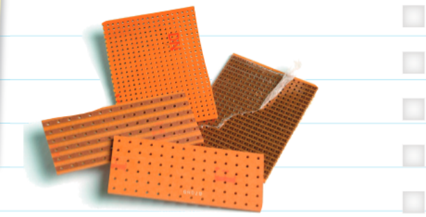
Stock forms - circuit boards
What are electronic systems?
Electronic systems form the foundation of modern technology by connecting various components together on printed circuit boards (PCBs). An electronic system works by taking electrical energy from an input source, processing this signal through connected components, and using it to power an output device. Think of it like a pathway where electricity flows from one point to another, being modified along the way to perform useful functions.
Think of an electronic system as a well-organized highway system - electricity enters at one point, travels along designated paths (tracks), and arrives at its destination where it performs a specific task.
Understanding printed circuit boards (PCBs)
Printed circuit boards serve as the backbone for electronic systems. These boards consist of copper foil that has been bonded onto a base material called a substrate. The most common substrate materials are glass reinforced plastic (GRP) or paper reinforced phenolic resin. GRP tends to be more expensive but offers better durability, while phenolic resin provides a cost-effective option commonly found in household appliances.
The copper foil creates pathways called tracks that connect different components together. You can often spot these fine copper lines on a PCB - they appear green because the board has been coated with a protective lacquer to prevent corrosion and damage.
Material Selection Trade-off:
- GRP substrates: Higher cost but superior durability and performance
- Phenolic resin substrates: Lower cost but suitable for basic household applications
Choose your substrate material based on the intended application and budget constraints.
Copper clad board manufacturing
When creating custom circuit boards, manufacturers start with copper clad board, which has a thin copper layer on either one or both sides of a GRP sheet. The copper tracks are formed by removing excess copper material using three main methods:
CNC router or miller: This computer-controlled machine cuts precise paths by programming the copper removal pattern into the system. Small cutters physically remove the unwanted copper and drill holes where needed. This method offers high precision and repeatability.
Photo-resist PCB process: This technique involves applying a special mask to the copper surface using ultraviolet light. The track layout gets drawn onto the copper with an ultraviolet mask, and the remaining copper gets dissolved away using a chemical solution like ferric chloride. This method works well for complex designs with fine details.
Etch resist masking: Here, the desired track pattern gets drawn directly onto the copper using an etch resist material, such as special tape or ink. The board then gets immersed in a chemical bath (typically ferric chloride) that removes all the unprotected copper, leaving only the masked areas intact.
Each manufacturing method has its strengths: CNC routing excels in precision and speed, photo-resist processes handle complex patterns well, and etch resist masking offers simplicity for basic designs.
Voltage and current fundamentals
Understanding voltage and current helps you work safely with electronic components and choose appropriate materials for your circuits.
Voltage represents the electrical energy needed to push electric charge along a pathway. We measure voltage in volts (). For reference, domestic homes in the UK operate at , while smaller electronic devices use much lower voltages. For example, AA or AAA batteries provide , mobile phone batteries typically supply , and car batteries operate at .
Current describes the quantity of electrical charge flowing through a circuit, measured in amperes (amps or ). Household appliances like electric kettles might draw , but electronic components on circuit boards typically operate using much smaller currents measured in milliamps (). Remember that , so most electronic circuits work with tiny fractions of an amp.
Safety Consideration: Always check voltage and current ratings before connecting components. Exceeding these ratings can damage components or create safety hazards. When in doubt, start with lower voltages and gradually increase while monitoring the circuit behaviour.
Voltage and Current Comparison:
High Voltage Applications:
- UK mains electricity:
- Car battery:
Low Voltage Applications:
- Mobile phone battery:
- AA battery:
Current Examples:
- Electric kettle:
- LED indicator:
- Microcontroller circuit:
Working with stripboard
Stripboard offers a convenient alternative to creating custom PCBs for prototype circuits and simple projects. These boards come pre-made with copper tracks already arranged in parallel lines across the surface of the GRP substrate.
 When using stripboard, you need to plan your circuit layout carefully to ensure components connect properly across the existing tracks. You can create breaks in the tracks or add links between tracks to achieve the desired circuit functionality. This flexibility makes stripboard excellent for educational projects and testing circuit designs before committing to a custom PCB.
Stripboard is particularly valuable for prototyping because it allows you to test and modify your circuit design without the time and cost of manufacturing a custom PCB. Once you've proven your design works, you can then create a professional PCB layout.
PCB manufacturing process example
Creating a printed circuit board using etch resist involves several key steps that require careful attention to detail and safety procedures.
Worked Example: PCB Manufacturing Using Etch Resist Method
Step 1: Design Planning Design your track layout on paper, planning where each component will connect and how the copper pathways should run.
Step 2: Pattern Transfer Transfer this design onto the copper board surface using an etch resist pen to draw the tracks directly onto the copper.
Step 3: Chemical Etching Immerse the marked board into a ferric chloride solution, which will dissolve away all the unprotected copper areas.
Step 4: Final Cleaning Rinse the board thoroughly to remove any remaining chemical solution, leaving you with clean copper tracks ready for component soldering.
This process requires careful handling of chemicals and proper ventilation, but it provides an excellent way to create custom circuit boards for specific applications.
Safety Warning: Always work in a well-ventilated area when using ferric chloride or other etching chemicals. Wear protective gloves and eye protection, and follow all safety guidelines provided with the chemicals.
Summary
Key Points to Remember:
- Electronic systems connect components on PCBs to process electrical signals from inputs to outputs
- PCBs use copper tracks on GRP or phenolic substrates to create electrical pathways
- Three main methods exist for creating copper tracks: CNC machining, photo-resist processing, and etch resist masking
- Voltage (measured in volts) provides the energy to move electrical charge, while current (measured in amps) represents the amount of charge flowing
- Stripboard offers pre-made parallel copper tracks for prototyping and simple circuit construction