Resistors (AQA GCSE Design and Technology): Revision Notes
Stock forms - Resistors
Understanding electrical fundamentals
Before exploring resistors in detail, you need to grasp three essential electrical concepts that work together in every circuit. These form the foundation of how resistors function and why they're so important.
Voltage acts like electrical pressure in a circuit. Just as water pressure pushes water through pipes, voltage provides the driving force that pushes electrical current through conductors. Higher voltage means more potential energy available to move electrons around a circuit. We measure voltage in volts (V).
Current represents the actual flow of electrical charge through a conductor. Think of it as the rate at which electrons move past any given point in a circuit. Current flows from high voltage to low voltage, and we measure it in amperes or amps (A). The amount of current flowing depends on both the voltage applied and the resistance in the path.
Resistance opposes the flow of current, much like friction opposes motion. Every material and component in a circuit has some resistance, which makes it harder for current to flow. We measure resistance in ohms (Ω). Materials with low resistance (like copper wire) allow current to flow easily, while materials with high resistance (like rubber) block current flow almost completely.
These three quantities are connected by Ohm's law, which states that voltage equals current multiplied by resistance: . This fundamental relationship helps us calculate unknown values in circuits and understand how components interact.
What resistors do in circuits
Resistors are components specifically designed to provide controlled amounts of resistance in electronic circuits. They serve several critical functions that make electronic devices work safely and effectively.
The primary job of resistors is controlling current flow. By adding resistance to a circuit path, they limit how much current can flow to sensitive components. This protection prevents damage from excessive current that could burn out delicate parts like LEDs or microprocessors.
Resistors also create specific voltage levels within circuits. When current flows through a resistor, it causes a voltage drop across that component. Engineers use this principle to create the exact voltages needed by different parts of a circuit, ensuring each component receives appropriate power levels.
Additionally, resistors help set timing in circuits, philtre unwanted signals, and provide reference voltages for measurements. They're essential building blocks found in virtually every electronic device.
Types of resistors and their applications
Fixed resistors
Fixed resistors provide a constant resistance value that doesn't change during normal operation. These are the most common type, used wherever you need predictable, stable resistance. They come in various power ratings and precision levels to suit different applications.
Variable resistors
Variable resistors allow you to adjust their resistance by turning a shaft or moving a slider. This adjustability makes them perfect for user controls and circuit adjustments.
 You encounter variable resistors daily in volume controls, dimmer switches, and speed controls. They enable users to modify circuit behaviour without rewiring, making devices more versatile and user-friendly.
Light dependent resistors (LDRs)
Light dependent resistors change their resistance based on light intensity. In bright conditions, their resistance drops significantly, while darkness causes their resistance to increase dramatically. This light sensitivity makes them excellent sensors for automatic lighting systems, security alarms, and camera exposure controls.
Thermistors
Thermistors are temperature-sensitive resistors that change resistance as temperature varies. Most decrease in resistance as temperature rises, making them valuable temperature sensors and control elements. You'll find them in thermostats, temperature monitoring systems, and circuits requiring temperature compensation.
Circuit symbols for resistors
Electronic diagrams use standardised symbols to represent different components clearly and universally. Understanding these symbols is essential for reading circuit diagrams and designing electronic systems.
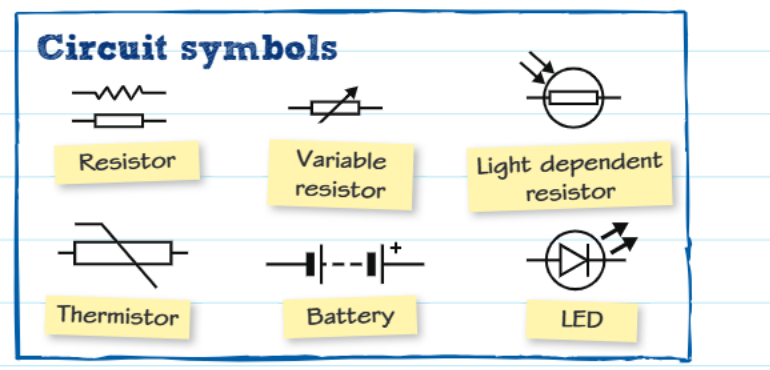 The basic resistor symbol appears as a zigzag line, representing the opposition to current flow. Variable resistors add a diagonal arrow through this zigzag, indicating their adjustable nature. Light dependent resistors are shown with a circle containing the zigzag pattern, with light arrows pointing towards it. Thermistors use the basic zigzag with a diagonal line through it, symbolising their temperature sensitivity.
These symbols allow engineers worldwide to communicate circuit designs without language barriers, making electronic diagrams universally readable.
Resistor colour coding system
Since resistors are often too small for printed numbers, manufacturers use a colour band system to indicate resistance values. This coding system provides a reliable way to identify component values quickly and accurately.
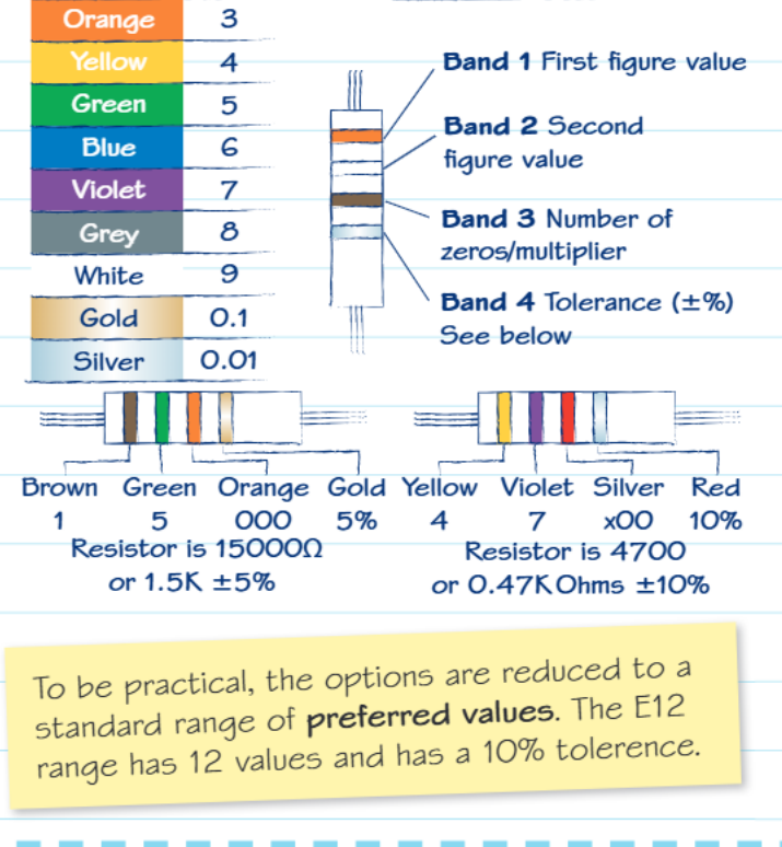
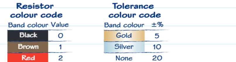 The colour coding assigns each colour a specific numerical value. Black represents 0, brown represents 1, red represents 2, and the sequence continues through orange (3), yellow (4), green (5), blue (6), violet (7), grey (8), and white (9).
 Reading resistor colour bands
Most resistors have four coloured bands that you read from left to right. The first two bands give you the significant digits of the resistance value. The third band serves as a multiplier, indicating how many zeros to add or what decimal factor to apply. The fourth band shows the tolerance, indicating how accurate the stated value is.
For example, a resistor with brown, green, orange, and gold bands would read as: 1 (brown) and 5 (green) for the base number 15, then 3 zeros (orange) for a multiplier of 1000, giving 15,000 ohms or 15 kilohms. The gold band indicates 5% tolerance, meaning the actual value could be anywhere from 14,250 to 15,750 ohms.
Tolerance and standard values
The tolerance band tells you how precisely the resistor matches its stated value. Gold bands indicate ±5% accuracy, silver indicates ±10%, and no fourth band means ±20% tolerance. Higher precision resistors cost more but provide better circuit performance when exact values matter.
Manufacturers produce resistors in standard value series rather than every possible combination. The E12 series contains 12 preferred values with 10% tolerance, covering the range needed for most applications while keeping manufacturing costs reasonable.
Worked example: LED protection circuit
Worked Example: LED Protection Circuit
Let's examine a practical calculation showing how resistors protect components in real circuits. Consider an LED circuit powered by a 9-volt battery, where the LED requires 13 milliamps of current and has a forwards voltage drop of 3.1 volts.
Step 1: Determine the voltage that must be dropped across the protection resistor. Since the battery supplies 9 volts and the LED uses 3.1 volts, the resistor must drop the remaining:
Step 2: Apply Ohm's law to find the required resistance. Using , with 5.9 volts to drop and 0.013 amps of current:
Step 3: Select the nearest standard value. Since resistors come in standard values, you'd select the nearest available option, which is 470Ω in the E12 series. This slightly higher value provides a safety margin, ensuring the LED receives slightly less than maximum current, extending its lifespan.
Key Points to Remember:
-
Ohm's law () is fundamental - this relationship applies to all resistor calculations and helps you solve circuit problems
-
Different resistor types serve specific purposes - fixed resistors provide stability, variable resistors enable control, LDRs respond to light, and thermistors sense temperature
-
Color coding follows a logical pattern - the first two bands give digits, the third gives the multiplier, and the fourth shows tolerance
-
Circuit symbols are universally standardized - learning these symbols lets you read electronic diagrams from anywhere in the world
-
Resistors often protect other components - they limit current flow and create appropriate voltage levels for sensitive electronic parts