Boolean Logic Diagrams (OCR GCSE Computer Science): Revision Notes
📚 Revision Notes
Boolean Logic Diagrams
Logic Gates Overview
- Logic gates are the basic building blocks of digital circuits. Each gate represents a different type of operation on binary input values (1 and 0).
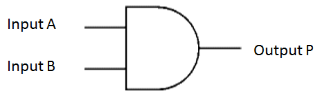
AND Gate (Conjunction)
- Logic Symbol:
- Operation: Outputs 1 only when both inputs are 1. Otherwise, the output is 0.
Truth Table
| A | B | A AND B |
|---|---|---|
| 0 | 0 | 0 |
| 0 | 1 | 0 |
| 1 | 0 | 0 |
| 1 | 1 | 1 |
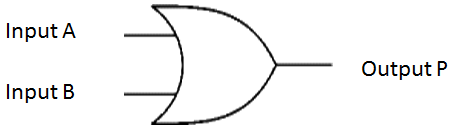
OR Gate (Disjunction)
- Logic Symbol:
- Operation: Outputs 1 if either or both inputs are 1. If both inputs are 0, the output is 0.
Truth Table
| A | B | A OR B |
|---|---|---|
| 0 | 0 | 0 |
| 0 | 1 | 1 |
| 1 | 0 | 1 |
| 1 | 1 | 1 |
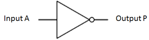
NOT Gate (Negation)
- Logic Symbol:
- Operation: Outputs the inverse of the input. If the input is 1, the output is 0; if the input is 0, the output is 1.
Truth Table
| A | NOT A |
|---|---|
| 0 | 1 |
| 1 | 0 |
Combining Boolean Operators
When combining logic gates, more complex operations can be represented by combining multiple gates into circuits. For example:
A AND B OR NOT A
| A | B | A AND B | NOT A | (A AND B) OR NOT A |
|---|---|---|---|---|
| 0 | 0 | 0 | 1 | 1 |
| 0 | 1 | 0 | 1 | 1 |
| 1 | 0 | 0 | 0 | 0 |
| 1 | 1 | 1 | 0 | 1 |
Logic Gate Problem Solving
-
Understanding the Truth Tables: The truth tables are used to evaluate the output for every combination of inputs. They help in designing and solving logic circuits.
-
Problem Example: Given a circuit with multiple gates, use the truth table to find the output for each input combination.
infoNote
Key Points to Remember
- The three basic gates: AND, OR, and NOT can be combined to solve complex logic problems.
- By using truth tables, the behaviour of the logic gates for all possible input combinations can be determined.