Orthographic Drawing (Junior Cert Applied Technology): Revision Notes
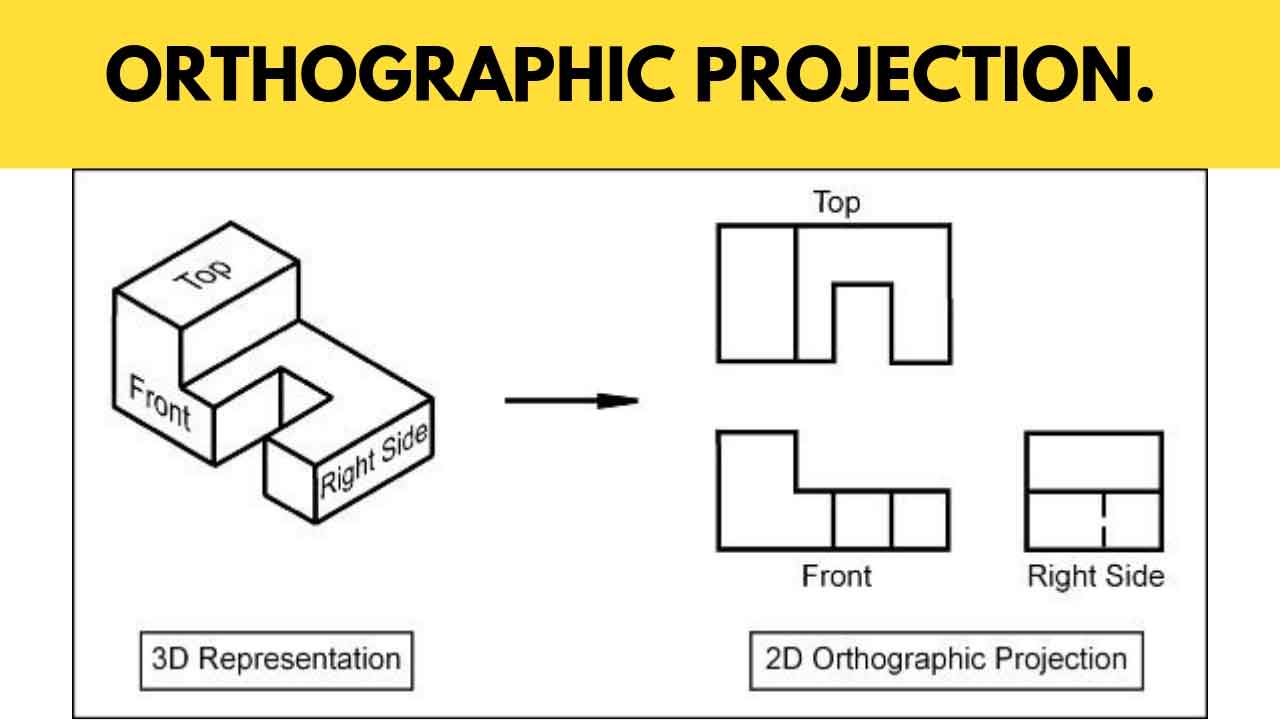
Orthographic Drawings
Orthographic drawings are an important tool in technology for clear communication of design details. They help produce accurate copies by showing multiple views of a 3D object.
Definitions
- Orthographic Drawing: A way to show 3D objects in 2D using multiple views.
- Principle of Projection: Explains how an object's size and shape are shown compared to the projection plane in these drawings.
- First Angle Projection: The object is in the first section; views are projected onto vertical and horizontal planes from the top-left. Common in Europe and Asia.
- Third Angle Projection: The object is in the third section; views are projected from the bottom-left. Standard in the United States.
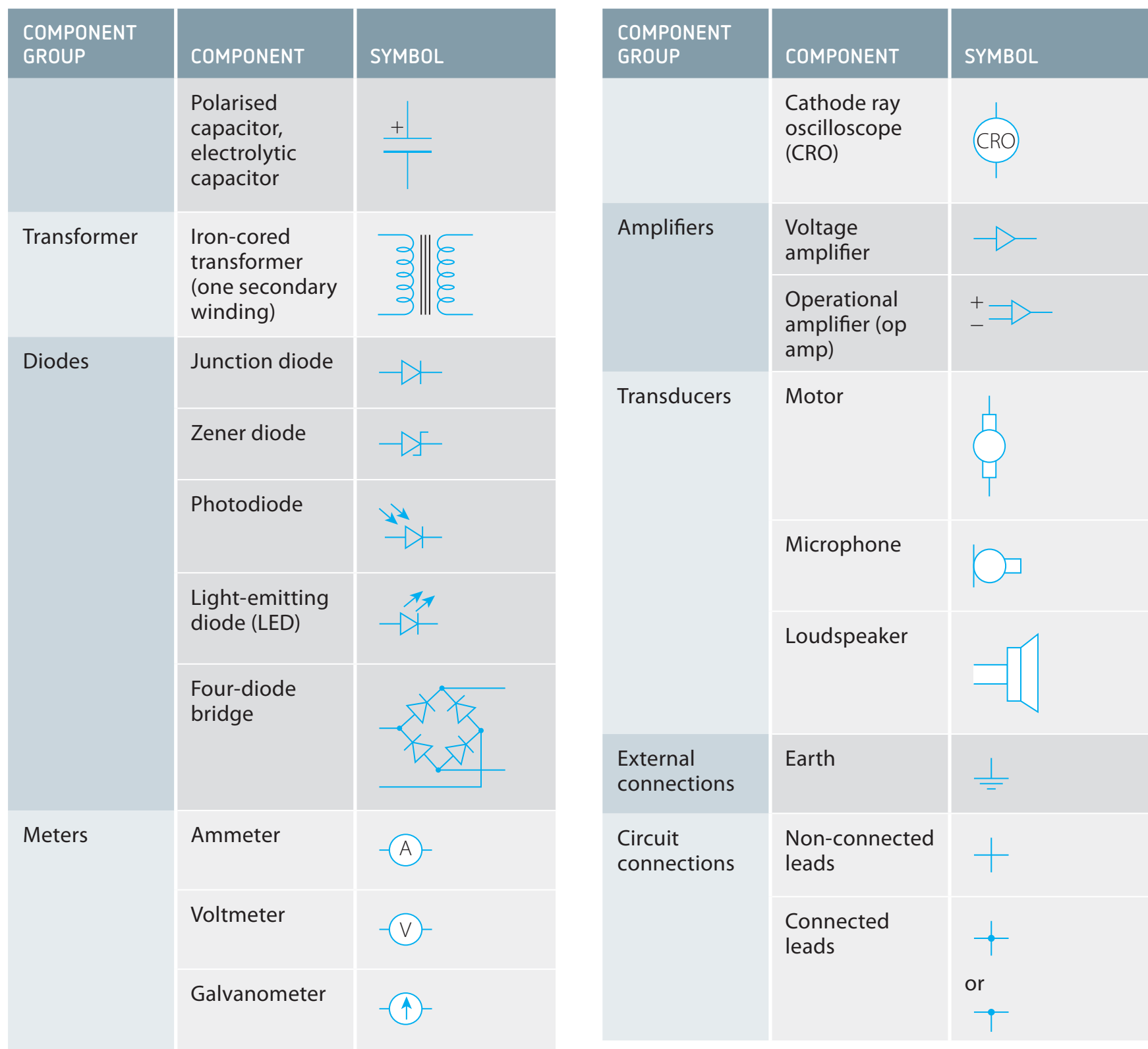
- Common Symbols: Indicators in technical drawings for details and instructions.
Principles of Orthographic Projection
Orthographic projections include top (plan), front (elevation), and side (end elevation) views. These views are arranged and aligned properly on the projection plane for a consistent understanding.
The projection plane is an imaginary surface where the object's views are shown, crucial for the alignment and scaling of views.
Worked Example
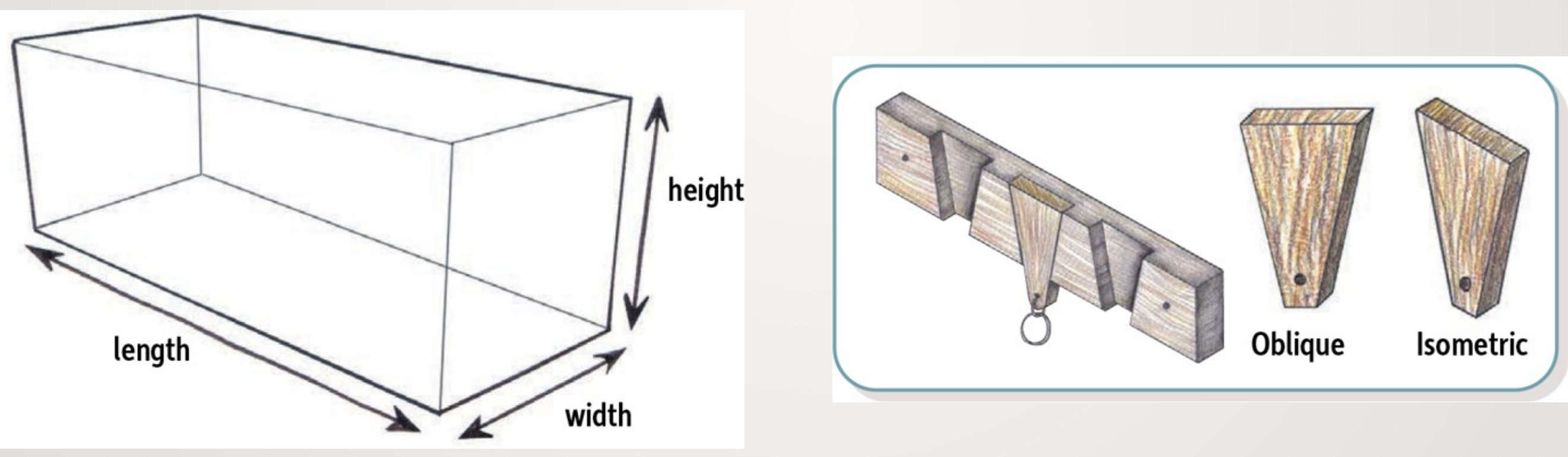
- Object: Simple rectangular block
- Identify Views: Find top, front, and side views.
- Project Views: Use first or third angle techniques.
- Annotate: Add dimensions and symbols.
Creating Orthographic Drawings
To make orthographic drawings:
- Traditional Tools: Use rulers, compasses, and set squares.
- Begin with sketching the main view (usually the front view).
- Place the top view directly above the main view and the side view in line with them.
- Use guidelines to align views.
- Add dimensions and symbols.
- CAD Software: In CAD, enter dimensions accurately and use software tools to produce multiple views smoothly.
Worked Example
- Example: Draw a simple mechanical part.
- Hand Techniques: Sketch with traditional tools.
- CAD Commands: Enter dimensions and commands in software for precise rendering.
Common Symbols and Notations
Orthographic drawings use symbols and notations to provide information, including hidden lines for unseen edges, centrelines for symmetry, and dimension lines for measurements.
Real-World Applications
Orthographic drawings are key in industries like construction for blueprints, mechanical engineering for making parts like gears, and electronics for circuit layouts. They give detailed guidance necessary for manufacturing and building.
Summary
Orthographic drawings are crucial in technology for clear communication.
- Use of first and third angle projections.
- Steps for creating drawings manually and with CAD.
- Importance of symbols in various industries.
- Understanding orthographic symbols and notation prevents misunderstandings.