Drilling (Junior Cert Engineering): Revision Notes
Drilling
Drilling is one of the most common manufacturing processes used to create holes in materials. It involves using a rotating cutting tool called a drill bit to remove material and form cylindrical holes. Understanding different drilling equipment, techniques, and safety procedures is essential for successful manufacturing operations.
Drilling operations are found in almost every manufacturing environment, from simple home workshops to complex industrial facilities. Mastering these fundamental skills opens doors to many engineering and manufacturing careers.
Types of drilling equipment
Pillar drilling machine
A pillar drilling machine is a floor-standing piece of equipment designed for accurate hole drilling operations. This robust machine consists of several important components that work together to provide precise drilling capabilities.
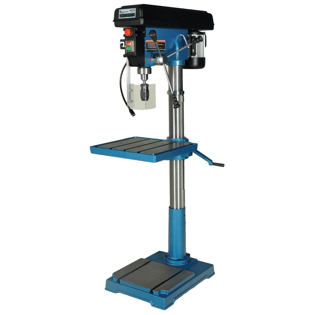
The main parts of a pillar drilling machine include:
- Motor: Provides the power to rotate the drill bit
- Chuck: Holds and secures the drill bit in place
- Feed lever: Controls the downward movement of the drill bit
- Belt guard: Safety cover that protects the drive belt system
- Adjustable depth stop: Limits how deep the drill can penetrate
- Table: Provides a flat surface to support the workpiece
- Column: Vertical support that allows the table to be adjusted for height
- Base: Heavy foundation that provides stability
- Emergency stop: Safety feature for immediate machine shutdown
The machine uses a stepped pulley system to change drilling speeds. By moving the belt to different sized pulleys, operators can adjust the rotational speed to suit different materials and drill sizes.
Hand drills
Hand drills are portable tools suitable for light drilling operations where a drilling machine cannot be used or where electrical power is not available.

Manual hand drill: This traditional tool is operated entirely by hand power. It features a holding handle, driving handle, and bevel gears that convert the rotational motion from the driving handle to the chuck. A breast plate allows the operator to apply steady pressure while drilling.
Battery-operated hand drill: Modern cordless drills are powered by rechargeable batteries, making them highly portable and convenient. They often come with spare batteries to ensure continuous operation. These drills can operate in forwards and reverse directions, making them useful for both drilling holes and driving screws.
Electric hand drill
Electric hand drills provide more power than manual versions and are ideal for drilling operations that cannot be performed on a drilling machine.
Key components include the chuck for holding drill bits, a switch for controlling operation, and a power lead for electrical connection. These drills work much faster than manual alternatives and require less physical effort from the operator.
Drill bits and cutting tools
Twist drills
Twist drills are the most commonly used type of drill bit. They are manufactured from high-speed steel and feature a complex geometry designed for efficient cutting.

Drill anatomy: Understanding the parts of a twist drill helps in selecting and using them correctly:
- Body: The main cutting portion with helical flutes
- Shank: The part held in the chuck or machine spindle
- Flutes: Spiral grooves that remove swarf and allow cutting fluid to reach the cutting edges
- Cutting edges: Sharp edges that actually cut the material
- Web: Central core that provides strength
- Point angle: Usually 118° for general purpose drilling
Types of shanks:
- Parallel shank: Used in chucks, typically for drills up to 13mm diameter
- Taper shank: Held directly in machine spindles or laith tailstocks for larger drills
Body clearance: The drill body diameter is slightly smaller than the cutting edge diameter to reduce friction during drilling. This design feature prevents the drill from binding in the hole and reduces heat generation.
Special purpose drills
Slow helix drills: These have a smaller rake angle and are specifically designed for drilling thermoplastics, brass, and bronze materials where standard drills might grab or tear the material.
Drill accessories
Drill drift: A wedge-shaped tool used to remove taper shank drills from machine spindles. A wooden block should be placed on the machine table to prevent damage during removal.
Morse taper sleeves: Used when the taper shank of a tool is too small for the machine socket. They provide an adapter to hold tools securely in drilling machine spindles and laith tailstocks.
Drilling machine operation
Safety procedures
Critical Safety Requirements
Safe operation of drilling equipment is crucial to prevent accidents and injuries:
- Never use the drilling machine without a chuck guard fitted
- Ensure there is no risk of hair or clothing getting caught in rotating parts
- Always remove the chuck key before starting the machine
- When changing belts, ensure the machine is switched off and the belt guard is replaced
- Never attempt to clean swarf by hand while the machine is running
- Ensure work is firmly gripped and properly supported
- Check that drill speed is appropriate for the material and drill size
Workholding methods
Proper workholding is essential for safe and accurate drilling operations.
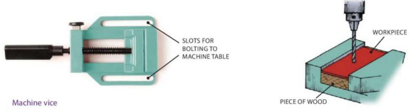
Machine vice: The most common method for holding work during drilling. The vice has slots in its base for bolting to the machine table. When drilling through work, place a piece of scrap wood underneath to protect the vice from drill damage.
Important workholding considerations:
- Position the centre punch mark accurately under the drill point before starting
- Use cutting fluid when required for the material being drilled
- Reduce pressure when the drill is breaking through to prevent binding
- Never drill into the vice jaws or machine table
Speed and feed calculations
Drilling machine speed depends on several factors that must be considered for optimal results.
Factors affecting spindle speed:
- Drill size: Larger drills require slower speeds
- Material type: Softer materials can be drilled at higher speeds
- Coolant use: Using cutting fluid allows higher speeds
Speed calculation formula:
Where:
- = Spindle speed in rev/min (RPM)
- = Cutting speed in metres/min
- = Drill diameter in millimetres
Worked Example: Speed Calculation
For a 6mm diameter drill in material with a recommended cutting speed of 30m/min:
Therefore, set the machine to approximately 1,600 RPM for optimal cutting conditions.
Feed: This refers to how fast the drill penetrates the material. Too much pressure can cause the drill to overheat, bind, or break. Too little pressure may cause the drill to rub without cutting, dulling the cutting edges.
Drilling techniques
Basic drilling methods
Locating hole centres: Use intersecting lines to mark the hole position, then centre-punch the intersection. Position the work so the drill point fits into the punch mark without deflexion.
Drilling sheet metal: Exercise extra care to avoid excessive pressure that could cause the drill to catch and spin the workpiece. Clamping the sheet metal between thicker pieces and increasing the point angle to about 140° helps achieve cleaner holes.
Special hole types
Understanding different hole types is crucial for proper fastening and assembly operations:
Pilot hole: A small hole drilled before using a larger drill. This keeps the larger drill centred and reduces the cutting load on its chisel edge.
Tapping size hole: Drilled smaller than the intended thread size to allow for thread cutting. The hole must be smaller than the tap to provide material for the thread form.
Clearance hole: Slightly larger than the bolt, stud, or screw passing through it. When bolting two parts together, both parts need clearance holes for easy assembly.
Blind hole: Does not go completely through the material. Common in engine blocks where a through-hole is not practical or desired.
Advanced drilling operations
Countersinking: This process enlarges the opening of a hole to accommodate the heads of countersunk screws and rivets. A special countersink bit creates the angled recess, or a standard twist drill can be used if ground to the correct angle.
Counterboring: This involves increasing hole diameter to a specific depth, usually to accommodate screw heads like allen screws or cheese head screws. The enlarged portion allows the fastener head to sit flush with or below the surface. A counterboring drill bit has a pilot that guides it in the original hole.

Worked Example: Counterboring Process
Step 1: Drill the pilot hole to the required diameter Step 2: Select appropriate counterboring bit with correct pilot size Step 3: Set depth stop to required counterbore depth Step 4: Apply steady pressure while counterboring to required depth Step 5: Check final dimensions with appropriate measuring tools
Using reamers
Reamers produce very smooth and accurately sized holes. A slightly undersized hole is first drilled, then the reamer finishes it to precise dimensions. Reamers are made from high-speed steel and come in various types:
- Hand reamers: Have square ends for tap wrench operation
- Machine reamers: Used in drilling machines or lathes
- Taper pin reamers: Create tapered holes for taper pins
Reamers must always be turned clockwise and should be used with appropriate cutting fluid for best results. Never reverse the direction of rotation as this will damage the reamer cutting edges.
Cutting fluids and coolants
Cutting fluids serve two important purposes in drilling operations: they cool the cutting tool and workpiece while also lubricating to reduce friction.
Benefits of using cutting fluids:
- Cutting tools last longer
- Higher machining speeds are possible
- Better surface finish is achieved
- Chips and swarf are carried away more effectively
How cutting fluids work:
- As a coolant: Carries away heat generated during cutting, keeping tools and workpieces at safe temperatures
- As a lubricant: Reduces friction between the tool and material, decreasing heat generation
Fluid selection: The choice of cutting fluid depends on the material being machined and the type of operation. Different materials require different cooling and lubrication properties to achieve optimal results.
Common fluid options include:
- Mild steel: Soluble oil
- High carbon steel: Soluble oil or paraffin
- Cast iron: Dry cutting with compressed air for cooling
- Brass: Dry cutting or soluble oil
- Aluminium: Soluble oil or paraffin
- Copper: Soluble oil or lard oil
The most efficient method of applying cutting fluid is through a pump system that continuously circulates the fluid through a philtre, ensuring clean fluid reaches the cutting area throughout the operation.
Key Points to Remember:
-
Safety first: Always use chuck guards and proper workholding methods when drilling. Never operate equipment without safety devices in place.
-
Speed matters: Larger drills need slower speeds, while softer materials can be drilled faster. Use the formula to calculate appropriate spindle speeds.
-
Choose the right tool: Different drilling operations require specific tools - pilot holes for large drills, reamers for precision holes, and special bits for countersinking and counterboring.
-
Use cutting fluids wisely: Select the appropriate cutting fluid for your material to extend tool life, improve surface finish, and enable higher cutting speeds.
-
Practice proper technique: Always centre-punch hole locations, reduce pressure when breaking through materials, and ensure work is securely held before beginning any drilling operation.