Axonometric Plane (Leaving Cert DCG): Revision Notes
Axonometric Plane
The axonometric plane is a fundamental concept in pictorial projection that allows us to create accurate three-dimensional representations of objects. Understanding this concept is crucial for producing high-quality isometric and axonometric drawings in technical graphics.
What is the axonometric plane?
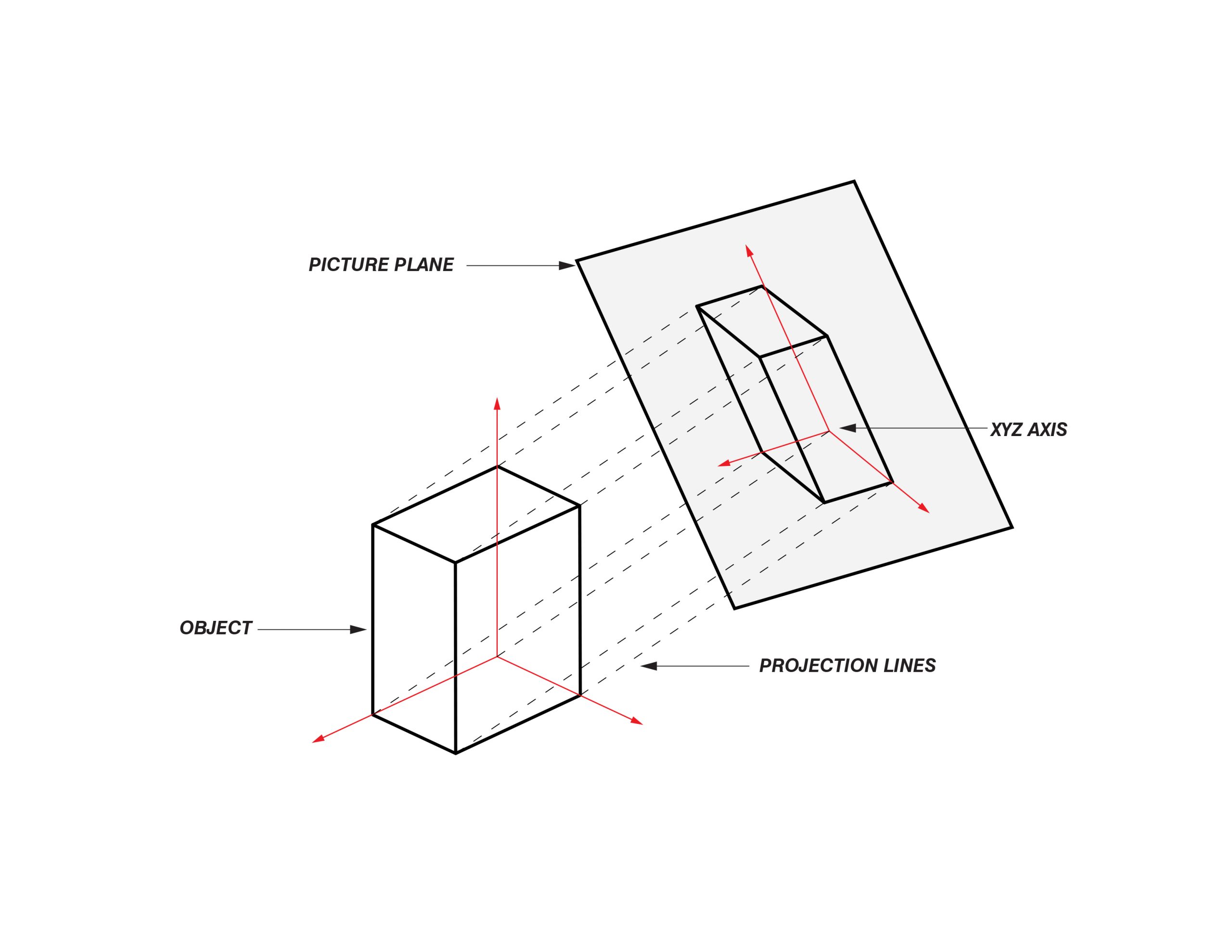
The axonometric plane is a specially positioned reference plane used in pictorial projection systems. When we project lines from an object perpendicularly onto this plane, we obtain either an isometric or axonometric view of that object.
Think of the axonometric plane as a "viewing screen" that captures the three-dimensional appearance of an object in a specific way. This analogy helps visualise how the plane functions as an intermediary between the 3D object and the 2D drawing.
The key characteristic of the axonometric plane is that it's positioned at a particular angle to the standard horizontal, vertical, and end vertical planes. This positioning ensures that all three principal directions of an object appear equally foreshortened in the resulting projection.
How the axonometric plane works
The axonometric plane functions by creating equal angles with the three main reference planes - horizontal, vertical, and end vertical. When an object is tilted at , the plane creates these equal angular relationships, which is why the resulting projection shows the object's three main faces at equal angles.
In the pictorial view, the axonometric plane appears as its true shape. This is important because it means we can work directly on this plane to create accurate measurements and proportions.
The isometric projection that results from this method maintains consistent scaling along all three axes.
Creating true isometric projections
The axonometric plane method
The axonometric plane method offers a systematic approach to creating true isometric drawings. Instead of relying on estimated angles and proportions, this method uses the geometric relationship between orthographic views and the axonometric plane to ensure accuracy.
This method starts with standard orthographic projections - the front elevation, end elevation, and plan view of the object. These views provide all the dimensional information needed to construct the isometric projection accurately.
Step-by-step construction process
Worked Example: True Isometric Construction Process
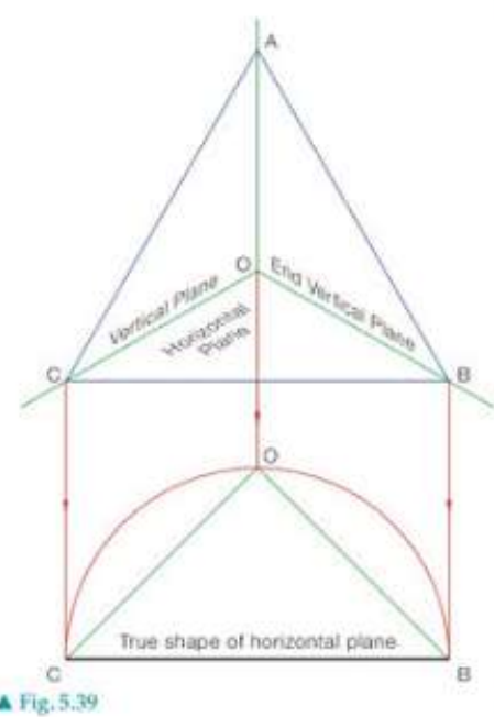
Step 1: Setting up the framework Begin by drawing the axonometric plane as an equilateral triangle ABC. This triangle represents the true shape of the horizontal plane as it appears in the axonometric projection. Draw the lines of intersection between the horizontal, vertical, and end vertical planes. These lines form the background framework for your construction.
Step 2: Transferring dimensions To draw the isometric projection accurately, you need both orthographic views - the plan and end elevation. Use these views to determine the true shape of the triangular portion of the horizontal plane. The measurements from your orthographic views can be transferred directly to construct the isometric form. Focus on finding key points and dimensions from your elevations and plan view.
Key features and benefits
The axonometric plane method offers several advantages for technical drawing:
- Accuracy: Unlike freehand isometric sketching, this method ensures precise proportions and angles
- Systematic approach: The step-by-step process reduces errors and provides consistent results
- Integration with orthographic views: Makes use of existing technical drawings rather than starting from scratch
- True measurements: Certain measurements can be taken directly from the construction, improving precision
The method is particularly valuable when creating technical illustrations where accuracy is essential, such as in engineering drawings or architectural presentations.
Remember!
Key Points to Remember:
- The axonometric plane creates true isometric projections by positioning itself at equal angles to the three main reference planes
- Start construction with an equilateral triangle ABC to establish the framework
- Use existing orthographic views (plan, front elevation, end elevation) as the source of accurate dimensions
- The axonometric plane appears as its true shape in the pictorial view, allowing for direct measurement and construction
- This method ensures consistent scaling and accurate proportions in the final isometric drawing