Sectional Planes (Leaving Cert DCG): Revision Notes
Sectional Planes
What are sectional planes?
A sectional plane is an imaginary cutting surface that slices through a three-dimensional object to reveal its internal structure. Think of it like using a knife to cut through an apple - the flat surface of the cut shows you what's inside. In technical drawing, these planes help us understand the interior details of complex objects that would otherwise be hidden from view.
The apple analogy is particularly useful for visualising sectional planes. Just as cutting an apple reveals its core, seeds, and flesh arrangement, sectional planes in technical drawing reveal the internal features and construction details of complex objects.
Sectional planes serve several important purposes in design and communication:
- They reveal internal features and construction details
- They help solve complex geometric problems involving solids
- They show how different parts of an object fit together
- They assist in creating accurate technical drawings
Types of sectional planes
There are four main types of sectional planes, each defined by its orientation relative to the standard reference planes (horizontal and vertical planes).
Horizontal section plane
A horizontal section plane cuts through an object parallel to the ground plane. When you look at the resulting cross-section from above, you see the plan view of the internal structure.
Key characteristics:
- Runs parallel to the horizontal reference plane
- Creates cross-sections visible in the plan view
- Shows the internal layout as seen from above
- Commonly used in architectural floor plans and mechanical drawings
Visualizing Horizontal Sections
When a horizontal plane cuts through a building, the resulting plan view shows room layouts, wall thicknesses, door positions, and other internal arrangements as if you're looking down from above.
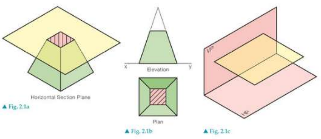
The diagram shows how horizontal planes intersect with geometric solids like pyramids and stepped blocks. Notice how the cross-hatched areas in the plan views represent the material that has been cut through by the sectional plane.
Vertical section plane
A vertical section plane cuts through an object perpendicular to the ground plane. This type of section reveals internal details that are visible in elevation views.
Key characteristics:
- Runs parallel to a vertical reference plane
- Creates cross-sections visible in elevation views
- Shows internal structure from the side
- Reveals height-related features and internal arrangements
Simply inclined section plane
A simply inclined section plane is tilted at an angle to one reference plane whilst remaining parallel to another. This creates more complex cross-sections that can reveal features not visible in standard horizontal or vertical sections.
Key characteristics:
- Inclined to one reference plane (usually horizontal or vertical)
- Parallel to the other reference plane
- Creates angled cross-sections
- Useful for showing sloped or angled internal features
Oblique section plane
An oblique section plane is the most complex type, as it's inclined to both horizontal and vertical reference planes. This creates cross-sections that show the object from unique angles.
Key characteristics:
- Inclined to both horizontal and vertical reference planes
- Creates the most complex cross-sectional shapes
- Reveals internal structure from compound angles
- Requires more advanced projection techniques to draw accurately
Understanding sectional views
When working with sectional planes, it's essential to understand how the 3D cutting action translates into 2D technical drawings:
- Cross-hatching: The areas where the sectional plane cuts through solid material are typically shown with diagonal lines or hatching patterns
- Hidden details revealed: Internal features that were previously hidden become visible in the sectional view
- Multiple views: Often, you'll need to show both the sectional view and the standard orthographic views to fully communicate the design
- Section lines: In technical drawings, the position and direction of the sectional plane is indicated by section lines with arrows
Reading Sectional Views
Cross-hatching serves as a visual indicator that distinguishes cut surfaces from visible edges. Different hatching patterns can also indicate different materials in complex assemblies.
Practical applications
Sectional planes are widely used across many fields:
- Architecture: Floor plans, building sections, and detail drawings
- Engineering: Mechanical assemblies, component analysis, and manufacturing drawings
- Product design: Internal mechanisms, material thickness, and assembly methods
- Medical illustration: Anatomical sections and surgical planning
Exam tips
Critical Study Strategies for Sectional Planes
When working with sectional planes in your DCG studies:
- Always identify the type of sectional plane first - this determines your approach
- Visualise the cutting action in 3D before attempting to draw the 2D result
- Pay attention to which view will show the cross-section most clearly
- Practice with simple geometric solids before moving to complex objects
- Remember that sectional planes can intersect curved surfaces as well as flat ones
Common mistakes to avoid:
- Confusing the type of sectional plane
- Forgetting to show cross-hatching on cut surfaces
- Mixing up which view shows the sectional details
Key Points to Remember:
- Sectional planes are cutting surfaces that reveal internal structure by slicing through 3D objects
- Four main types exist: horizontal, vertical, simply inclined, and oblique sectional planes
- Each type has specific characteristics based on its orientation to reference planes
- Cross-hatching indicates cut material in technical drawings and helps distinguish sectional views
- Sectional planes are essential tools for communicating complex internal details that cannot be shown in standard orthographic views