Traces of a Plane (Leaving Cert DCG): Revision Notes
Traces of a Plane
When studying projection systems, understanding how planes cut through solids is essential for creating accurate technical drawings. A trace of a plane refers to the line where a cutting plane intersects with the surface of a solid object or with the projection planes themselves.
The concept of plane traces is fundamental to technical drawing and geometric construction. Mastering this concept will help you understand more complex projection problems and sectional view creation.
What are sectional planes?
A sectional plane is an imaginary flat surface that cuts through a three-dimensional object to reveal its internal structure. These cutting planes help us understand what's inside a solid without having to physically cut it open. Think of it like slicing through a loaf of bread - the cut surface shows you the inside structure.
Sectional planes can be positioned at different angles, and each type creates different traces when viewed in orthographic projection. The position and orientation of these planes determines what internal features become visible in the resulting technical drawings.
Key Concept: A sectional plane is always an imaginary cutting surface - it's a tool for visualisation and technical drawing, not a physical cut. Understanding this distinction is crucial for proper geometric construction.
Types of sectional planes
Understanding the four main types of sectional planes and their characteristics is essential for accurate projection work. Each type produces different trace patterns and reveals different aspects of the solid's internal structure.
Horizontal section plane
A horizontal section plane cuts through an object parallel to the ground plane. When this type of plane intersects a solid:
- The trace appears as a line in the elevation view
- The cross-section shape is fully visible in the plan view
- The cut surface is typically shown with hatching patterns
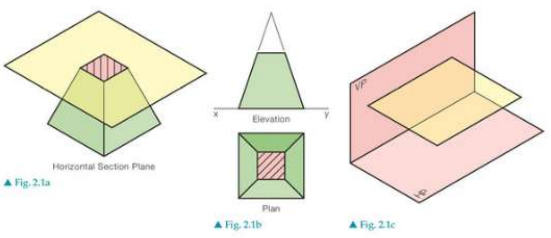
In the diagram above, you can see how a horizontal plane cuts through a pyramid, creating a square cross-section that's clearly visible in the plan view. Notice how the trace line in the elevation corresponds directly to the cutting plane's position.
Vertical section plane
A vertical section plane cuts through an object perpendicular to the ground plane. This type of cutting plane:
- Creates a trace line in the plan view
- Shows the full cross-section in the elevation view
- Reveals the internal profile of the object when viewed from the side
Simply inclined section plane
A simply inclined section plane is tilted at an angle from the vertical position but still maintains a straight orientation. These planes:
- Create angled trace lines in both plan and elevation views
- Produce cross-sections that may appear distorted in standard orthographic views
- Require careful construction to show the true shape of the cut surface
Simply inclined planes are more challenging to work with than horizontal or vertical planes because they don't align with the standard projection planes. This means the true shape of the cross-section often appears foreshortened in the standard views.
The simply inclined examples demonstrate how the cutting plane's angle affects the appearance of the resulting cross-section. The trace lines will be parallel in both views but at different angles.
Oblique section plane
An oblique section plane is positioned at complex angles to all the main projection planes. These are the most challenging to work with because:
- They create compound angles in multiple views
- The traces appear as skewed lines in both plan and elevation
- The true shape of the cross-section often requires auxiliary views to display correctly
Advanced Concept: Oblique section planes require the most sophisticated geometric construction techniques. They often need auxiliary views to show the true shape and size of the resulting cross-section.
Understanding traces in orthographic projection
When a sectional plane cuts through a solid, it creates several important elements that must be properly understood and represented:
Trace lines - These show where the cutting plane intersects with the projection planes or the solid's surface. They appear as straight lines in the orthographic views and indicate the exact position of the cutting plane.
Cross-sections - These show the actual shape created where the plane cuts through the solid. Cross-sections are typically filled with hatching patterns to distinguish them from other parts of the drawing.
Visible and hidden details - Sectional planes can reveal internal features that would normally be hidden, such as holes, cavities, or internal structures.
Construction Principle: The trace lines in different orthographic views must be consistent with each other. If you can construct the trace in one view, you should be able to project it accurately to the other views using standard projection techniques.
Practical applications
Understanding traces of planes is crucial for:
- Creating section views in technical drawings
- Solving complex geometric problems involving intersections
- Designing objects that need to show internal components
- Analysing how different cutting angles reveal various aspects of a solid
These skills are particularly important in engineering drawing, architectural sections, and mechanical design where internal structures must be clearly communicated.
Exam tips
Essential Exam Strategy:
- Always identify the type of sectional plane first (horizontal, vertical, simply inclined, or oblique)
- Remember that trace lines show where the plane intersects, while cross-sections show what the cut reveals
- Use proper hatching patterns to clearly indicate cut surfaces
- Check that your traces are consistent across different orthographic views
- Pay special attention to the direction and angle of trace lines - they must correspond between views
Summary
Key Points to Remember:
- Sectional planes are imaginary cutting surfaces that slice through solids to reveal internal structure
- Four main types: horizontal, vertical, simply inclined, and oblique planes
- Traces appear as lines showing where the cutting plane intersects surfaces or projection planes
- Cross-sections show the actual shape created by the cut and are indicated with hatching
- Different angles of cutting planes reveal different aspects of the same solid
- Consistency between views is essential for accurate geometric construction