Floor Plans, Elevation Plans, and Design Drawings (Grade 11 NSC Matric Mathematical Literacy): Revision Notes
Floor Plans, Elevation Plans, and Design Drawings
When working with plans and drawings, you need to understand three main types that serve different purposes in construction and manufacturing. Each type shows different information about buildings, structures, or objects, and understanding their differences is essential for reading and interpreting technical drawings correctly.
Understanding the three types of drawings
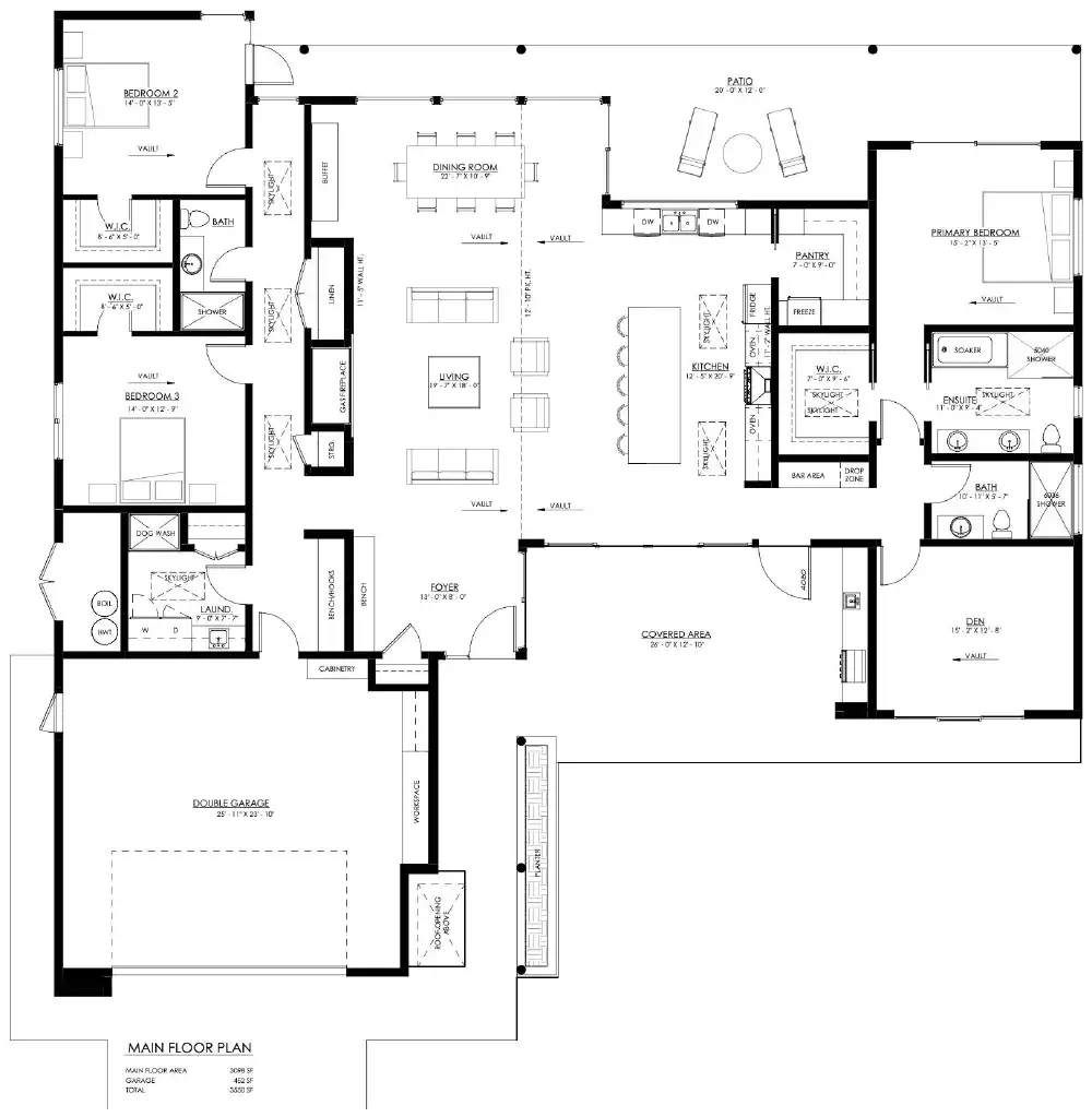
Floor plans are drawings that show you what a building looks like when viewed from directly above, without the roof. Think of it as if you were floating above the building looking down into it. These plans reveal the internal layout and help you understand how rooms connect to each other.
Elevation plans show you what a building looks like when viewed from the side. These drawings display the external appearance of the structure, including windows, doors, and the roof design. Each elevation plan shows a different side of the building.

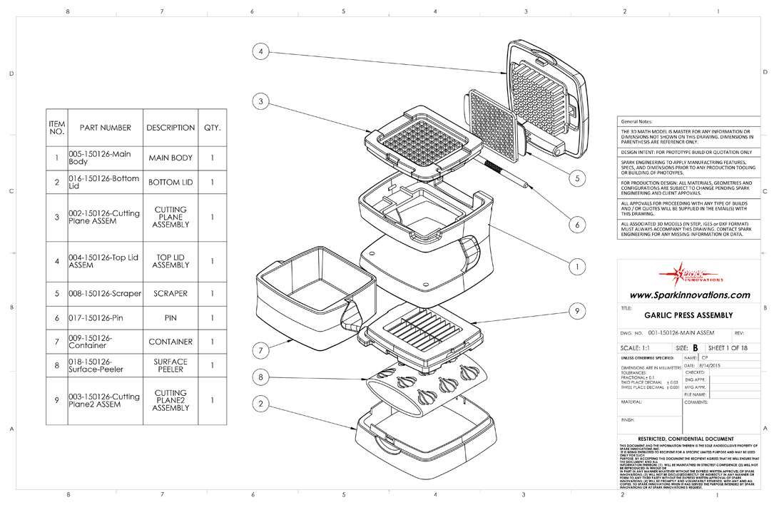
Design drawings are technical drawings that show you how to construct or manufacture specific items like furniture or clothing. These drawings include all the component parts and assembly instructions needed to create the finished product.
The key difference between these drawing types is their perspective: floor plans show the "bird's eye view" from above, elevation plans show the "side view" from ground level, and design drawings focus on individual components and assembly details.
Key skills for floor and elevation plans
When working with floor and elevation plans, you need to master several important skills that will help you interpret technical drawings accurately and extract useful information from architectural plans.
Describing building features
You must be able to identify and count specific features shown on plans. For example, you might need to determine how many rooms, windows, or doors appear in a house plan. This requires careful observation of the symbols and layouts used in the drawings.
Worked Example: Counting Features
When examining a floor plan:
- Look for room boundaries (solid lines)
- Count window symbols (typically shown as breaks in walls)
- Identify door symbols (curved lines showing door swing)
- Check for special features like stairs or built-in furniture
Result: A typical house might show 3 bedrooms, 1 bathroom, 1 kitchen, 1 living room, 8 windows, and 6 doors.
Connecting floor plans to elevation plans
A crucial skill is matching features between different views of the same building. When you see a window on a floor plan, you should be able to identify where that same window appears on the elevation plans. This helps you understand the complete three-dimensional structure of the building.
Understanding compass directions in elevation plans
North, South, East, and West elevation plans can be confusing, but there's a logical system to understand them:
Understanding Elevation Plan Directions:
- The North Elevation plan shows the side of the building that faces North
- If you stand outside the building and look at the side shown on the North Elevation plan, you are actually facing South
- If you stand inside the building and look out through a window on the North Elevation side, you are looking North
- This same principle applies to all other elevation plans (South, East, West)
Remember: The elevation plan name tells you which direction that side of the building faces, not which direction you're looking from!
Many houses are built with their main windows facing North to maximize sunlight during winter months.
Using scale for accurate measurements
Plans are drawn to scale, which means every measurement on the drawing represents a specific real-world measurement. For example, if a plan uses a scale of 1:100, then 1 centimetre on the drawing represents 100 centimetres (1 metre) in reality.
To find actual dimensions, you measure the feature on the plan and multiply by the scale factor. If a room measures 3 cm on a 1:100 scale plan, the actual room length is:
Worked Example: Scale Calculations
Given: A door measures 2.5 cm on a plan with scale 1:50
Step 1: Identify the scale factor Scale factor = 50
Step 2: Calculate actual size Actual width = 2.5 cm × 50 = 125 cm = 1.25 metres
Step 3: Check if reasonable A door width of 1.25 metres is realistic ✓
Key skills for design drawings
When working with design drawings, focus on these essential skills that will help you understand how manufactured items are constructed and assembled.
Identifying the object and its purpose
Start by clearly describing what item the design drawing represents. Is it a piece of furniture, clothing, or another manufactured product? Understanding the purpose helps you interpret the drawing correctly.
Design drawings often include multiple views (front, side, top) of the same object, similar to how buildings have multiple elevation plans. Each view reveals different construction details and dimensions.
Measuring component dimensions
Design drawings include precise measurements for all parts. You must be able to read these dimensions accurately and create tables showing the size of each component. This information is essential for ordering materials and cutting parts to the correct size.
Understanding component parts
Every design drawing shows the different pieces needed to construct the final product. You need to identify each component, understand how they fit together, and describe the assembly process clearly.
Creating cutting lists
A cutting list shows all the individual parts needed to make an item, along with their dimensions and quantities. This list helps ensure you have enough material and can cut all pieces efficiently from larger sheets or boards.
Worked Example: Creating a Cutting List
For a simple wooden stool:
| Component | Quantity | Length | Width | Thickness |
|---|---|---|---|---|
| Top | 1 | 300mm | 300mm | 18mm |
| Legs | 4 | 400mm | 40mm | 40mm |
| Braces | 4 | 250mm | 25mm | 18mm |
Total material needed: 1 sheet 300×300×18mm + 4 pieces 40×40×400mm + 1 sheet 250×100×18mm
Exam tips and common mistakes
Common Mistakes to Avoid:
- Don't confuse compass directions: Remember that a North Elevation shows the north-facing side, but if you're looking at it from outside, you're facing south
- Always use the given scale: Never guess measurements - always calculate using the provided scale
- Read symbols carefully: Different line types and symbols have specific meanings in technical drawings
- Check your units: Make sure your final answers use the correct units (metres, centimetres, etc.)
- Be systematic: When counting features like windows or doors, work methodically to avoid missing any
Key Points to Remember:
-
Floor plans show the internal layout of buildings from above, elevation plans show external views from the side, and design drawings show how to construct specific items
-
Use the given scale to calculate actual dimensions by measuring the drawing and multiplying by the scale factor
-
Compass directions in elevation plans refer to which way that side of the building faces, not which direction you're looking
-
When working with design drawings, focus on identifying component parts, their dimensions, and how they fit together
-
Practice reading different types of plans regularly to build confidence in interpreting technical drawings accurately