DC Motors (HSC SSCE Physics): Revision Notes
DC Motors
Introduction to DC motors
A DC motor is an electric device that converts electrical potential energy into kinetic (movement) energy. The motor operates by using a coil of wire that carries electric current, positioned within a magnetic field. When current flows through the coil, the magnetic field exerts forces on it, creating a rotational force called torque. This torque causes the coil to spin continuously, producing mechanical motion.
Real-World Applications of DC Motors
DC motors are found throughout modern technology and are essential to our daily lives. From small household appliances like blenders and hair dryers to large applications such as suburban trains, DC motors provide the mechanical power needed for countless devices. Electric and hybrid vehicles are increasingly using DC motors as their primary power source.
The name "DC motor" comes from the fact that these motors run on direct current – electric current that flows in only one direction. This is different from alternating current (AC), which periodically reverses direction.
Torque on a current-carrying loop in a magnetic field
To understand how a DC motor works, we first need to examine what happens when a current-carrying wire is placed in a magnetic field.
Force on a current in a magnetic field
When an electric current flows through a wire positioned in a magnetic field, the wire experiences a force. The size of this force is given by the equation:
where:
- is the force (in newtons, N)
- is the length of the wire (in metres, m)
- is the current (in amperes, A)
- is the magnetic field strength (in tesla, T)
- is the angle between the direction of current flow and the magnetic field
The force is greatest when the current flows perpendicular (at right angles) to the magnetic field, making and .
Understanding torque
Torque is the rotational equivalent of force – it's a push or pull that causes an object to rotate around an axis. Consider opening a door: you apply a force to the door handle, and this creates a torque that rotates the door around its hinges.
The torque produced by a force depends on:
- The magnitude of the force ()
- The distance from the axis of rotation to where the force is applied ()
- The angle between the force direction and the line from the axis to the force application point ()
The torque is calculated using:
where is the torque (in newton-metres, N m). Torque is maximum when the force acts perpendicular to the line from the axis of rotation.
Rotation of a current-carrying loop
Now consider a rectangular loop of wire carrying current, positioned in a magnetic field as shown below.
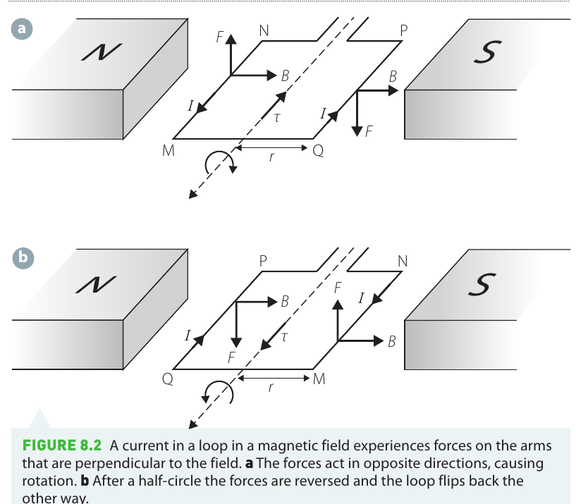
The wire on opposite sides of the loop experiences forces in opposite directions. For example, if the top section experiences an upward force, the bottom section experiences an equal downward force. These two forces don't cancel out – instead, they create a torque that causes the loop to rotate.
When we view the loop from the side during rotation, we can see how the torque changes:
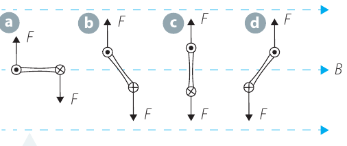
The rotation cycle proceeds through several stages:
- Stage a: The loop is aligned with the magnetic field. The torque is at its maximum, causing rapid rotation.
- Stage b: As the loop rotates, the torque decreases but is still present.
- Stage c: The loop is perpendicular to the field. The forces act along the same line, producing zero torque. However, the loop's momentum carries it past this balance point.
- Stage d: Past the balance point, the torque reverses direction, acting to push the loop back.
The Oscillation Problem
Without any intervention, the loop would reverse direction and oscillate back and forth around the balance point, eventually coming to rest due to friction. This is not useful for a motor that needs continuous rotation. This is why commutators are essential – they solve this fundamental problem by reversing the current at just the right moment.
Torque formula for a loop
The torque acting on a current-carrying loop in a magnetic field can be expressed as:
where:
- is the current through the loop (in amperes, A)
- is the area enclosed by the loop (in square metres, m²)
- is the magnetic field strength (in tesla, T)
- is the angle between the normal (perpendicular line) to the loop's plane and the magnetic field
This formula shows that torque can be increased by:
- Increasing the current
- Using a larger loop area
- Strengthening the magnetic field
Worked example: calculating current from torque
Worked Example: Calculating Current from Torque
A current-carrying loop sits in a magnetic field of magnitude . The coil has a cross-sectional area of . If the coil is positioned at an angle of to the field and experiences a torque of , what current must it carry?
Solution:
Step 1: Convert the area to SI units:
Step 2: The torque formula relates these quantities:
Step 3: Rearranging to solve for current:
Step 4: Substituting the values:
Step 5: Checking units: Since and , we have:
Therefore:
Components of a DC motor
A practical DC motor contains several essential components that work together to produce continuous rotation.
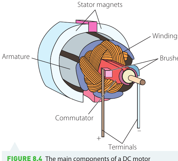
A DC motor consists of two main assemblies:
The stator
The stator is the stationary part of the motor that doesn't move during operation. It includes:
- The outer casing or housing that protects the motor
- The magnets (either permanent magnets or electromagnets) that create the magnetic field
- The input wires that supply electrical power
- The brushes that make sliding electrical contact with the rotating parts
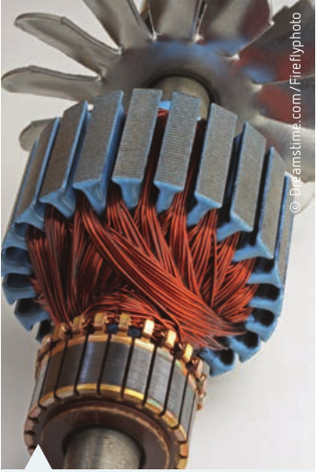
The rotor
The rotor is the part that rotates during motor operation. It consists of:
- The armature, which is the structure that holds and supports the coils
- The windings or coils of wire through which current flows
- The commutator, which reverses the electrical connections during rotation
The rotor is mounted on a shaft that transfers the rotational motion to the load (whatever the motor is driving).
Memory Aid: Stator vs Rotor
- STATOR = STATionary – the stator doesn't move
- ROTOR = ROTates – the rotor spins
This simple word association helps remember which component does what!
Commutators and brushes
The commutator is one of the most critical components in a DC motor. Without it, the motor would not be able to rotate continuously.
The problem commutators solve
As we saw earlier, a simple current-carrying loop in a magnetic field would oscillate back and forth rather than rotating continuously. The current in the coil must be reversed every half rotation to keep the torque acting in the same direction and maintain continuous rotation.
How commutators work
A commutator is essentially a reversing switch. It typically consists of a copper ring split into two halves (or more segments for motors with multiple coils), with insulating material separating the halves.
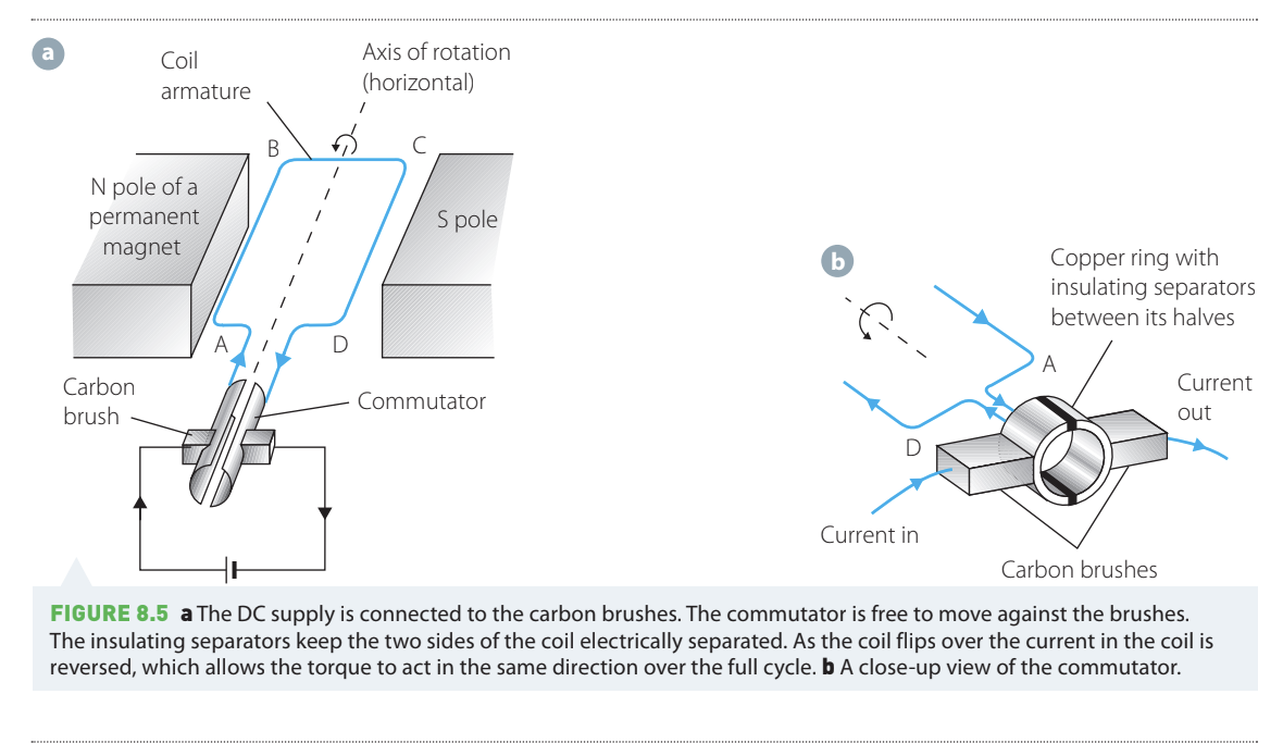
Carbon or graphite blocks called brushes press against the commutator and provide the electrical connection to the rotating coil. As the commutator rotates, different segments come into contact with each brush. At the moment when the coil passes through its balance point, the commutator switches which segment connects to which brush, effectively reversing the current direction in the coil.
Why Commutators Are Essential
The effect of commutators on motor operation is dramatic. Without commutators, the torque oscillates between positive and negative values, causing the loop to flip back and forth. With commutators, the torque is always in the same direction, maintaining continuous rotation. The torque still varies in magnitude but never reverses direction.
Think of the commutator as a "COMmuter" – it switches direction like a commuter changes trains!
The graphs below show the torque experienced by a coil over time:
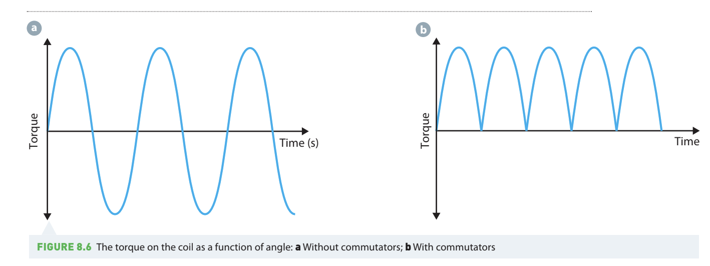
- Without commutators (left graph): The torque oscillates between positive and negative values, causing the loop to flip back and forth.
- With commutators (right graph): The torque is always in the same direction, maintaining continuous rotation. The torque still varies in magnitude but never reverses direction.
The coils
The coils in a DC motor are where the current flows, producing the forces that create torque. Several factors affect how well the coils function.
Multiple turns
Rather than using a single loop of wire, DC motors use coils with many turns. Each individual turn experiences a torque, and the total torque is the sum of all these individual torques:
where is the number of turns in the coil.
Increasing the number of turns increases the torque, making the motor more powerful and faster. However, more turns also make the coil larger and heavier, which can be a disadvantage in some applications.
Multiple coils at different angles
As a single coil rotates, the torque it experiences varies sinusoidally – it's maximum at some positions and zero at others. Most practical DC motors use multiple coils wound around the armature at different angles to each other.
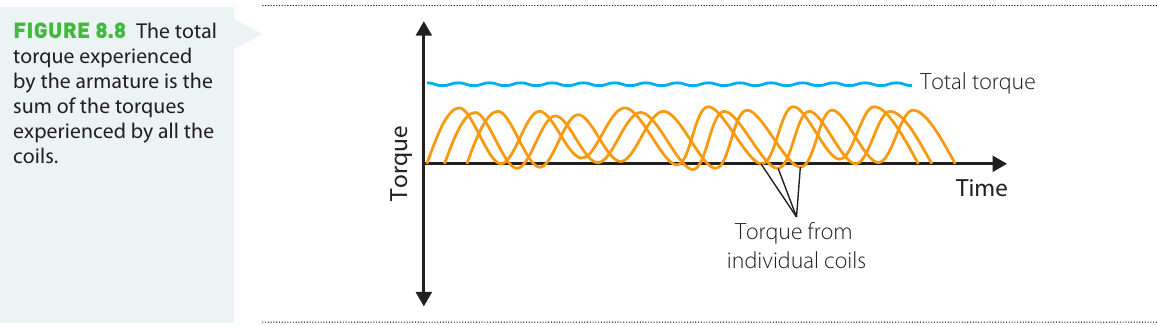
When multiple coils are positioned at angles to each other, as one coil experiences decreasing torque, another experiences increasing torque. The total torque on the armature is the sum of the torques on all individual coils. This arrangement provides:
- More consistent total torque throughout the rotation
- Smoother motor operation with less vibration
- Greater overall power output
Worked example: forces and torque on a multi-turn coil
Worked Example: Forces and Torque on a Multi-Turn Coil
A motor uses a -turn coil with dimensions by , as shown below. A current of flows through the coil. The coil is vertical and positioned in a magnetic field of directed upwards.
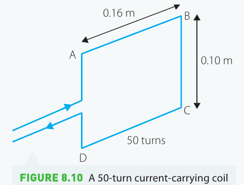
a) What is the magnitude and direction of the force exerted on side AB?
The force per unit length of wire carrying current in a magnetic field is:
For side AB, the current is perpendicular to the magnetic field, so and . With turns, there are lengths of wire in this section:
Using the right-hand rule, the force on side AB acts upward.
b) What is the magnitude and direction of the force exerted on side BC?
For side BC, the current flows parallel to the magnetic field (which is directed upwards), so and :
There is no force on side BC.
c) What is the total torque acting on the coil?
Torque is calculated using:
For side AB:
For side BC: (since the force is zero)
For side CD: (by symmetry)
For side DA:
Total torque:
d) In which direction will the coil begin to rotate?
Using the right-hand rule, the torque acts along the direction AB. If you point your fingers along AB and curl them following the rotation, your thumb points in the direction of the torque. The coil will rotate clockwise when viewed from the right side.
Magnets
The magnets in a DC motor create the magnetic field in which the coil rotates. Most motors use either permanent magnets or electromagnets as part of the stator.
Shaped magnets for constant torque
Many DC motors use specially shaped magnets rather than simple rectangular magnets. The shape of the magnet pole faces is designed to create a more uniform magnetic field that varies less in strength as the coil rotates.
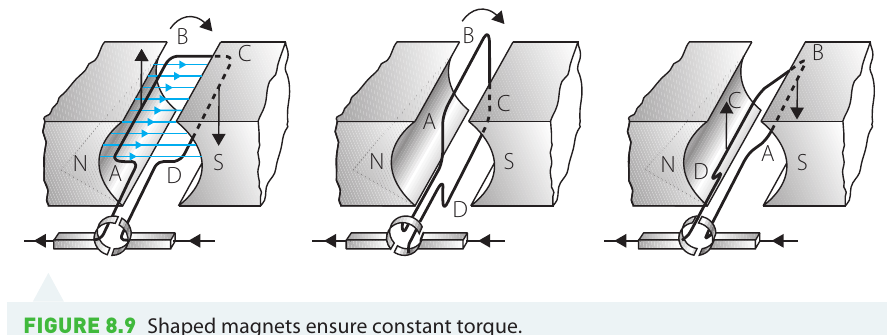
Benefits of Shaped Magnets
Shaped magnets help maintain more constant torque throughout the rotation cycle. This results in:
- Smoother motor operation
- More consistent speed
- Better overall performance
Some motors also use electromagnets with multiple coils wound at different angles around an iron core. Like shaped permanent magnets, these configurations increase the magnetic field strength and improve the smoothness of rotation.
Back emf
When a DC motor operates, it doesn't simply speed up indefinitely even though energy continues to be supplied. Instead, the motor accelerates until it reaches a steady rotational speed. Understanding why requires knowledge of electromagnetic induction.
What causes back emf
As the coil in a motor rotates, it moves through the magnetic field. This changing magnetic flux through the coil induces an emf (voltage) in the coil itself – this is the principle behind electromagnetic induction. According to Lenz's Law, this induced emf must oppose the change that caused it.
The induced emf in a motor is called back emf because it acts in the opposite direction to the applied voltage that powers the motor. The back emf effectively reduces the net voltage across the coil, which limits the current that can flow.
Effect on motor speed
How Back EMF Limits Motor Speed
The back emf increases as the motor spins faster:
- When the motor starts from rest, there is no back emf, so maximum current flows and the motor accelerates rapidly
- As the motor speeds up, the back emf increases, reducing the net voltage and limiting the current
- Eventually, the back emf becomes large enough that the reduced current provides just enough torque to overcome friction and maintain constant speed
- The motor reaches a steady rotational speed where energy input equals energy lost to friction and other resistive forces
This self-limiting behaviour prevents the motor from accelerating without limit and protects it from damage. The maximum speed of a DC motor is determined by the applied voltage and the strength of the back emf at that speed.
Investigation: make your own DC motor
Aim
Build a functioning DC motor, then investigate its performance characteristics. Develop a research question about what measurements will reveal about your motor's performance.
Materials
Research different designs for simple DC motors before selecting your approach. You will need:
- Wire for making coils
- A power source (battery)
- Magnets (permanent magnets)
- Materials for the armature and support structure
- A commutator (can be made from split pins or copper strips)
- Carbon or graphite for brushes
- Measuring equipment to test motor performance (stopwatch, ruler, etc.)
Consider looking at various designs to find one suitable for the available materials.
Risk assessment
Electrical equipment can be dangerous if used incorrectly, as it may cause electric shocks. To stay safe, always follow instructions from your teacher and use equipment according to the manual.
Consider what other hazards might be present in your specific design and how to manage them safely.
Method
- Collect all required equipment. Create a complete list of materials needed.
- If some equipment is unavailable, modify your design or select an alternative approach.
- Build your motor, ensuring it includes:
- A coil with multiple turns
- A commutator to reverse current direction
- Brushes for electrical contact
- A support structure to hold components in place
- Test your completed motor:
- Measure rotational speed (consider using sound recording or video to count revolutions)
- Measure power consumption
- Test reliability over multiple trials
- Minimise uncertainties by taking multiple measurements and calculating averages.
Results and analysis
Record all measurements including:
- Current and voltage during operation
- Rotational speed (revolutions per minute)
- Starting time (how long until reaching steady speed)
- Any variations or inconsistencies
Calculate the armature's rotational speed with appropriate uncertainty values.
Discussion
Compare your motor's performance with those built by other students. Consider:
- What design features produce higher speed?
- What features improve reliability?
- What trade-offs exist between different design choices?
- How do the number of turns, magnet strength, and other factors affect performance?
Conclusion
Summarise your key findings about DC motor design and performance factors that you discovered through building and testing your motor.
Remember!
Key Points to Remember:
-
DC motors convert electrical energy into kinetic energy through electromagnetic forces acting on current-carrying coils in a magnetic field.
-
Torque on a current loop is given by , where is the number of turns. Torque can be increased by increasing current, coil area, field strength, or number of turns.
-
Commutators are essential – they reverse the current direction every half rotation, preventing the motor from oscillating and enabling continuous rotation in one direction.
-
Multiple coils at different angles create smoother operation by maintaining more constant total torque throughout the rotation cycle.
-
Back emf limits motor speed – as the motor spins faster, it generates a voltage opposing the applied voltage, reducing current and establishing a maximum operating speed.