Truth Tables (AQA GCSE Computer Science): Revision Notes
Truth tables
What are truth tables?
A truth table is a systematic way of showing all possible combinations of inputs and their corresponding outputs for a logic system. Think of it like a complete list that shows what happens in every possible scenario.
Truth tables provide a methodical approach to understanding logic systems by presenting every possible input combination alongside its corresponding output. This systematic representation makes it impossible to miss any scenario, ensuring complete understanding of how a logic system behaves.
Truth tables are incredibly useful because they let you see exactly how a logic gate or circuit will behave in every situation. Each row in the table represents a different combination of inputs, and the final column shows what the output will be for that specific combination.
To understand this better, imagine learning to drive. You need to pass both a practical test and a theory test to get your driving license. We can create a truth table to show this logic:
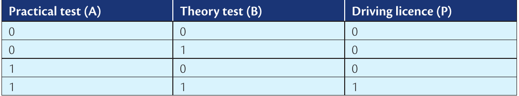
Practical Example: Driving License Logic
In the driving license example:
- Input A = Practical test result (0 = fail, 1 = pass)
- Input B = Theory test result (0 = fail, 1 = pass)
- Output = License granted (0 = no, 1 = yes)
You only get a driving license when both conditions are met - this demonstrates the logical AND operation that we'll explore in detail later.
Truth tables for basic logic gates
Logic gates are the building blocks of computer circuits. Each gate performs a specific logical operation, and truth tables help us understand exactly what each gate does. Let's explore the four main types you need to know for GCSE.
NOT gate (inverter)
The NOT gate is the simplest logic gate. It has just one input and always produces the opposite output. If you put in a 0, you get out a 1. If you put in a 1, you get out a 0. This is why it's also called an inverter - it inverts or flips the input signal.

The NOT gate symbol looks like a triangle with a small circle at the output end. The circle indicates that the signal is inverted - this is a universal symbol in logic diagrams that means "NOT" or "opposite".
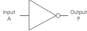
This gate is essential in computer circuits because it allows systems to create the opposite of any signal, which is needed for many logical operations.
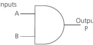
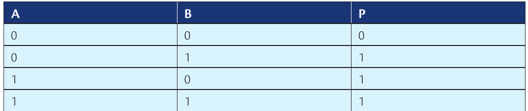
AND gate
An AND gate has two inputs and only produces a 1 output when both inputs are 1. Think of it like a door that needs two keys - you only get through (output = 1) when you have both keys (both inputs = 1).

Looking at this truth table, you can see that the output P is only 1 in the bottom row where both A and B equal 1. In all other cases, the output is 0. This is the defining characteristic of an AND gate - it requires all inputs to be true for the output to be true.
The AND gate is commonly used in security systems, where multiple conditions must be met before something is allowed to happen. For example, a bank vault might require both a key card AND a PIN code to open.
OR gate
An OR gate also has two inputs, but it produces a 1 output when either one input OR the other input (or both) equals 1. It's like having two different switches that can both turn on the same light.
Notice how the output P is 1 whenever at least one input is 1. Only when both inputs are 0 does the output become 0. This makes OR gates useful for situations where you want something to happen if any one of several conditions is met.
XOR gate (exclusive OR)
The XOR gate is more selective than a regular OR gate. It produces a 1 output only when exactly one input is 1, but not both. If both inputs are the same (both 0 or both 1), the output is 0.

The XOR gate is fundamentally different from the OR gate - it's "exclusive" because it excludes the case where both inputs are true. This makes it perfect for detecting when two signals are different from each other.
The XOR gate is particularly useful in computer systems for comparing values and detecting when two signals are different. It's also used in encryption and error detection systems.
Truth tables for combined circuits
Real computer circuits often combine multiple gates to create more complex logic operations. When gates are connected together, you can still use truth tables to work out what the overall circuit does.
Here's an example of combining an AND gate with a NOT gate:
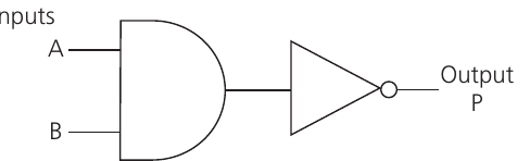
When analysing combined circuits, always work systematically from left to right through the circuit. Calculate the output of each gate before moving to the next one. This step-by-step approach ensures you get the correct final result every time.
To create the truth table for this combined circuit, you work through it step by step:
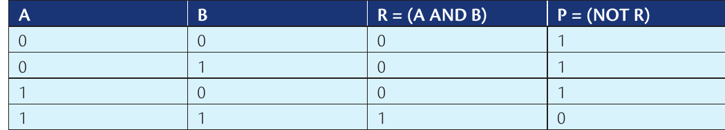
Worked Example: Creating a Combined Circuit Truth Table
Step 1: Identify the gates in sequence
- First gate: AND gate (inputs A and B, output R)
- Second gate: NOT gate (input R, output P)
Step 2: Work out intermediate results
- Calculate column R using AND gate rules
- Then apply NOT gate to R to get final output P
Step 3: Complete the table systematically This creates what's called a NAND gate - the opposite of an AND gate.
Understanding how to create truth tables for combined circuits is crucial because most real computer systems use combinations of basic gates to perform complex operations. By breaking down the circuit into stages and working through each step, you can predict exactly how any logic circuit will behave.
Key Points to Remember:
- Truth tables show every possible input combination and its corresponding output - they're like a complete instruction manual for logic circuits
- NOT gates always flip the input - 0 becomes 1, and 1 becomes 0, making them essential for creating opposite signals
- AND gates need ALL inputs to be 1 to produce a 1 output - think "both this AND that must be true"
- OR gates need at least ONE input to be 1 to produce a 1 output - think "either this OR that (or both) must be true"
- XOR gates are picky - they only output 1 when inputs are different, making them perfect for comparison operations
- Combined circuits require systematic analysis - work through each gate in sequence to build the complete truth table