Series and Parallel Circuits (Junior Cert Applied Technology): Revision Notes
Series and Parallel Circuits
Electric circuits are vital components in electrical systems, forming the framework for many devices, from household gadgets to industrial equipment. There are two main ways to arrange components in a circuit: series and parallel.
Definitions
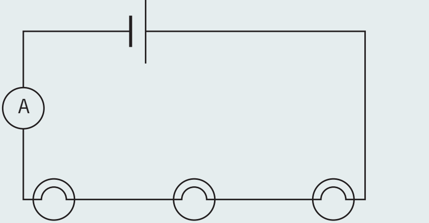
- Series Circuit: Components line up in a row, so there's only one path for current to flow:
- Every part carries the same current.
- Total voltage equals the sum of each part's voltage.
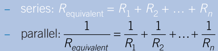
- Total resistance is the sum of all resistances, making it greater.
- If one part stops working, the whole circuit stops.
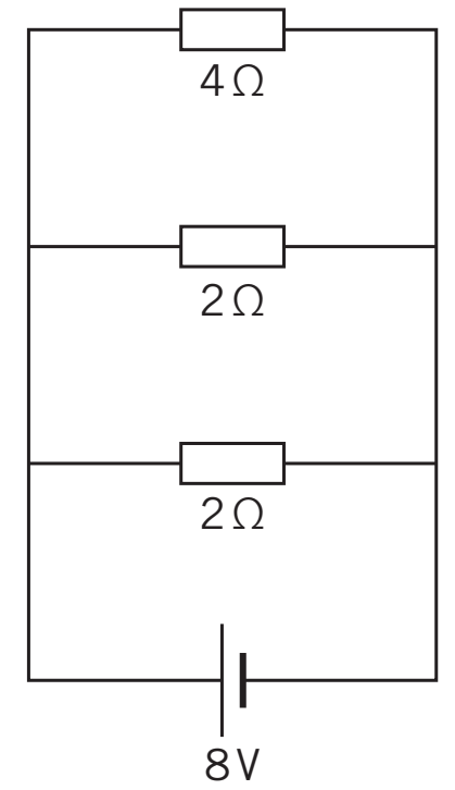
- Parallel Circuit: Components create several paths for electricity:
- Every part gets the same voltage.
- Total current equals the sum of the current in each path.
- Total resistance is less than any single resistance.
- If one path fails, others still work.
| Feature | Series Circuit | Parallel Circuit |
|---|---|---|
| Pathway | Single path | Multiple paths |
| Current | Same through each component | Splits into different paths |
| Voltage | Sum of individual voltages | Same across all parts |
| Effect of Component Failure | Whole circuit stops | Other paths keep working |
| Resistance | Increases with more parts | Decreases with more paths |
Electrical Connections
Components connect differently in series and parallel circuits, each with specific rules:
- Series Configuration: Components are in a single line, so current flows through each one sequentially.
- Parallel Configuration: Each part connects straight to the power source, creating multiple paths for current.
Worked Example
- Step 1: Pick basic parts like resistors or bulbs for each setup.
- Step 2: Connect them to a single power source using guides.
- Step 3: Use Ohm's Law to find and show current, voltage, or resistance.
Advantages and Disadvantages
Each circuit type has its own pros and cons regarding performance and reliability.
- Series Advantages:
- Easy to design and build.
- Uses less material than parallel circuits.
- Series Disadvantages:
- A single failure can stop the circuit.
- Voltage drops with each additional resistor.
- Parallel Advantages:
- More reliable, as each part works on its own.
- Steady voltage ensures even lighting.
- Parallel Disadvantages:
- Complex to design and connect.
- Needs more materials.
Worked Example
- Step 1: Imagine setting up holiday lights.
- Step 2: Compare setups based on their pros and cons.
- Step 3: Decide the best setup, explaining your reasoning.
Effects of Wiring LEDs
How LEDs are wired affects their performance, brightness, and lifespan.
- Series LEDs: If one fails, they all turn off.
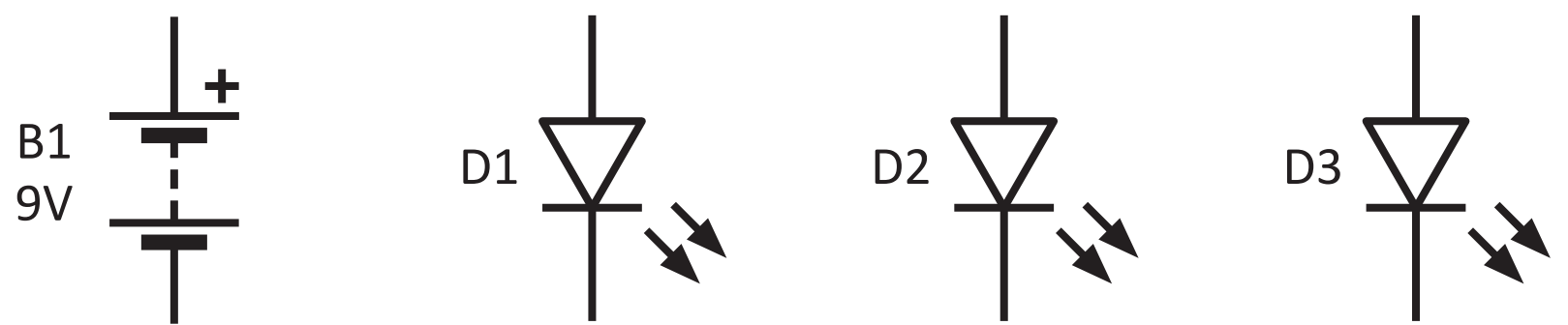
- Parallel LEDs: Keeps performance steady but uses more electricity.
Worked Example
- Step 1: Wire a small group of LEDs both ways.
- Step 2: Compare their brightness and how reliable they are.
- Step 3: Try removing an LED to see what happens.
Resistance in Circuits
Understanding resistance in series and parallel setups is crucial for designing circuits:
- Resistance in Series: Add the resistances together for a higher total resistance.
- Resistance in Parallel: Overall resistance is lower than any single part, allowing more current and improving efficiency.
Worked Example
- Step 1: Calculate total resistance for series with example values.
- Step 2: Use different values to find parallel resistance.
- Step 3: Discuss how total resistance affects circuit function and efficiency.
Application Problem
You are designing a lighting system for a workshop that needs to be reliable. The system will have 4 LED lights, each requiring 3V and drawing 0.5A. You have a 12V power supply available. Which circuit configuration would be most suitable and why?
Summary
Review the main points, highlighting key differences between series and parallel circuits. Consider performance impacts and which setup is best for specific uses. Highlight the importance of knowing resistance for circuit design.