Graphics & Design (Junior Cert Engineering): Revision Notes
Graphics & Design
Graphics and technical drawings are essential tools for communication in engineering and design. They help us show how objects look, explain how to make things, and develop new ideas. Visual images make it much easier to understand complex information, which is why drawings are so widely used in technology and manufacturing.
What are graphics?
Graphics, also known as technical drawing, serve several important purposes in engineering:
- Communication - They show others exactly what you're thinking
- Description - They explain how objects appear and function
- Instruction - They provide step-by-step guidance for making things
- Development - They help you work through and improve your ideas
Different types of drawings are used depending on what information needs to be communicated. Understanding when to use each type is crucial for effective technical communication.
Orthographic projection (2D drawing)
Orthographic projection is a method that shows objects in excellent detail by using multiple flat, two-dimensional views. Instead of trying to show everything in one complex drawing, this technique breaks the object down into separate views from different angles.

The system works by projecting views from three main directions:
- Front elevation - the view from the front
- End elevation - the view from the side
- Plan - the view from above (looking down)
This approach is extremely useful because it shows the true shape and size of each surface without any distortion. When you look at an object straight-on from any direction, you see its actual proportions, making it perfect for manufacturing and construction work.
Three-dimensional (3D) or pictorial drawing
Sometimes we need to show objects so they appear three-dimensional, giving viewers a better understanding of the overall shape and how different parts relate to each other. There are two main methods for creating these 3D representations.
Oblique projection
Oblique projection creates a 3D appearance by drawing one face in its true shape and projecting the other surfaces from it, typically at a angle.
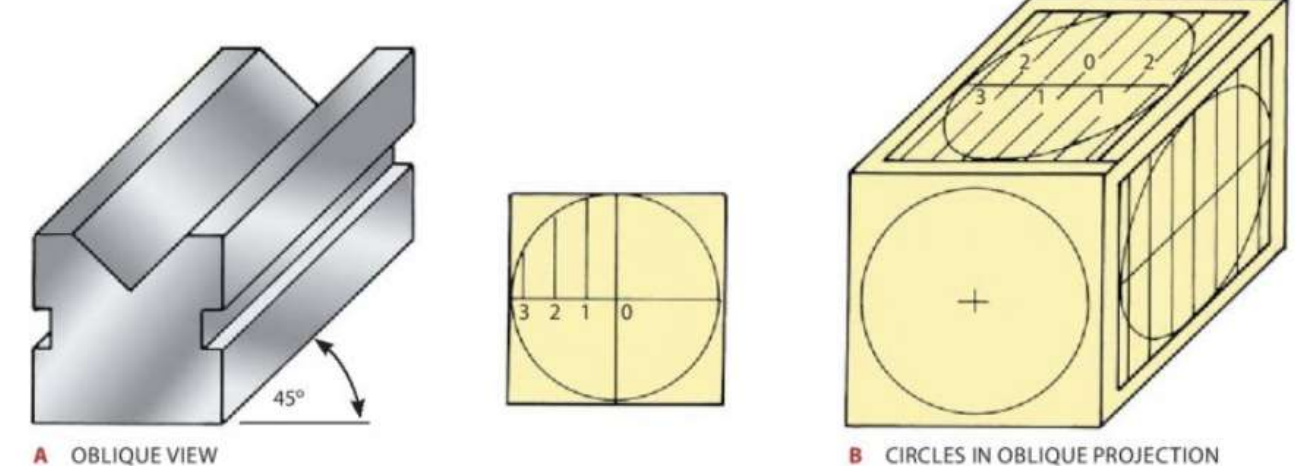
This method works particularly well when there's lots of detail on the front face that needs to be shown clearly. An important characteristic of oblique projection is that circles on the front face stay as perfect circles, but circles on the angled surfaces appear as ellipses (flattened circles).
The technique involves drawing ordinates (measurement lines) at convenient distances in one section of a circle, then transferring these measurements to create the elliptical shapes on the other surfaces.
Isometric projection
Isometric projection uses a different approach where the main lines are drawn vertically and at angles to both the left and right sides. This creates a more balanced 3D appearance.
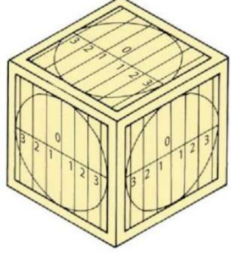
In isometric drawings, all circles appear as ellipses, which can be constructed using the same ordinate method described for oblique projection. This projection method gives a very realistic three-dimensional appearance and is commonly used in technical illustrations.
Freehand sketching
Freehand sketching is an incredibly useful skill that allows you to quickly communicate ideas without needing drawing instruments. These sketches are perfect for developing concepts, explaining designs, and recording thoughts when formal drawing tools aren't available.
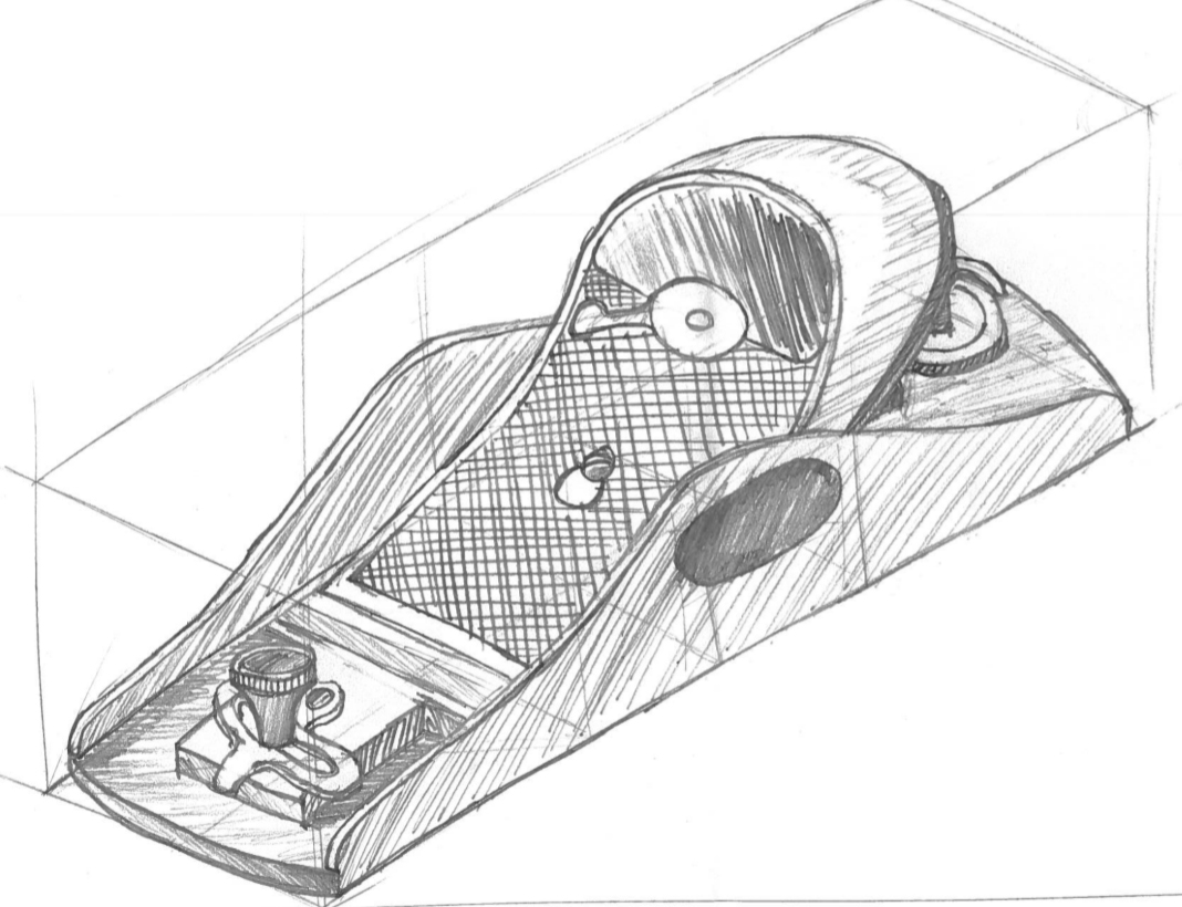
Essential requirements for good freehand sketches
Your freehand sketches should be:
- Clear and neat - easy for others to understand
- Well proportioned - showing correct relative sizes
- Properly spaced - not cramped or too spread out
- Sufficiently detailed - including enough views and information
- Dimensioned - showing important measurements when needed
Hints for freehand sketching
Paper choice: Isometric grid paper and square grid paper are extremely helpful for freehand work. They help you maintain straight lines and good proportions without much effort.
Pencil selection: Use a reasonably soft pencil (like HB grade) that doesn't have too sharp a point. This prevents the lines from being too harsh and makes sketching more comfortable.
Drawing techniques:
- Draw horizontal lines from left to right if you're right-handed, or right to left if you're left-handed
- Draw vertical lines from top to bottom
- For inclined lines, turn your paper so you can draw them as horizontal lines
- Keep your hand on the inside of curves - you may need to rotate the paper to achieve this
Sketching circles
Drawing good circles freehand requires a systematic approach:
Step-by-step Circle Sketching Method
- Start by drawing horizontal and vertical centre lines
- Mark off distances equal to the radius on each side of the centre
- Join these points with light curved lines
- Complete the circle by drawing over these construction lines
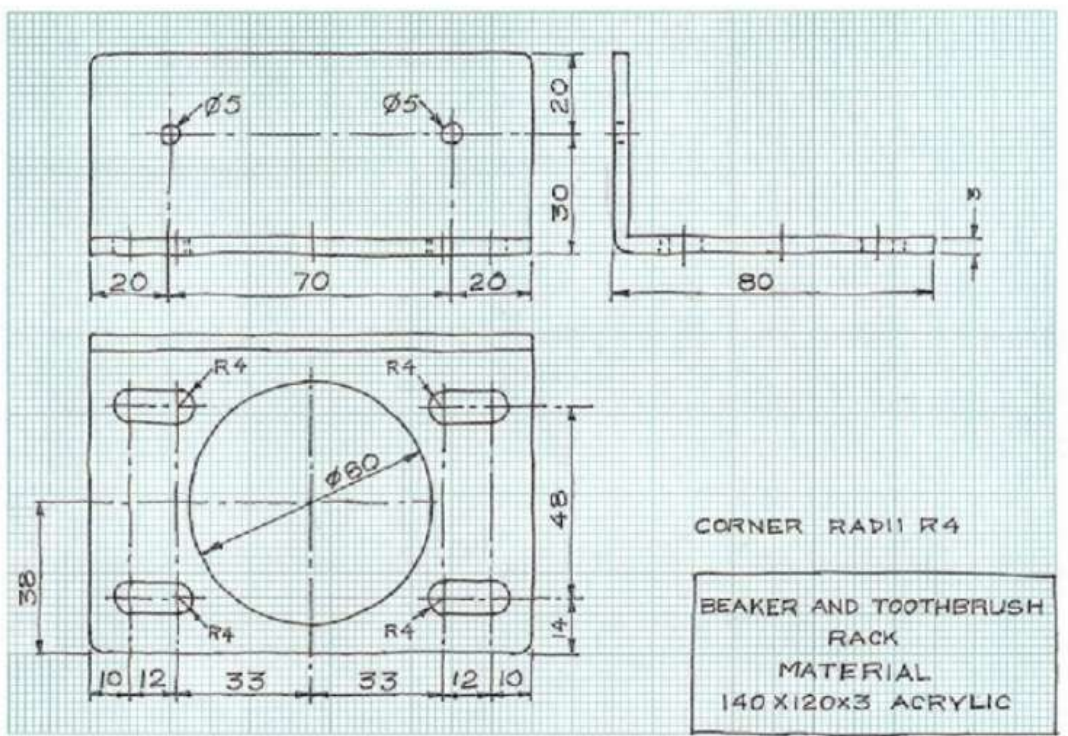
Working drawings
Working drawings are comprehensive technical documents that provide all the information needed to manufacture an article. These drawings are crucial in industry because the person creating the drawing usually isn't the same person who will make the actual product.

Key characteristics of working drawings
Working drawings must include:
- Complete orthographic projections of every component
- Precise measurements and dimensions
- Material specifications - what each part should be made from
- Assembly information - how parts fit together
- Manufacturing notes - any special processes required
- Clear labelling - identifying each component
The information must be presented clearly and completely because manufacturing personnel need to understand exactly what to make without having to guess or make assumptions.
Computer-aided design (CAD) packages
Modern technology has revolutionised technical drawing through computer-aided design software. Programmes like AutoCAD and Solidworks have become essential tools in the design process.
Advantages of CAD
CAD software offers numerous benefits over traditional drawing methods:
- Speed and efficiency - drawings can be created and modified much faster
- Automatic generation - once a 3D model is complete, the software can automatically produce orthographic views and dimensions
- Easy modification - change one drawing and all related views update automatically
- Precision - computer accuracy eliminates human measurement errors
- Storage and sharing - digital files can be easily stored, copied, and shared
- Professional appearance - consistent line weights and text styles
CAD packages allow designers to fully explore their ideas by creating detailed 3D models that can be viewed from any angle, tested virtually, and easily modified as the design develops.
Remember!
Key Points to Remember:
-
Orthographic projection uses multiple 2D views (front elevation, end elevation, and plan) to show objects in complete detail without distortion
-
Oblique projection creates 3D drawings with one true face and others projected at angles, keeping front-face circles as perfect circles
-
Isometric projection uses vertical lines and angles to create balanced 3D representations where all circles appear as ellipses
-
Freehand sketching is essential for quick communication - use grid paper, soft pencils, and proper drawing techniques for best results
-
Working drawings must contain complete information for manufacturing, including dimensions, materials, and assembly details - clarity is crucial since the drawer and maker are usually different people