Constructing Electrical and Electronic Circuits (Junior Cert Science): Revision Notes
Constructing Electrical and Electronic Circuits
Introduction
Building electrical and electronic circuits is a fundamental skill in physics and technology. In this topic, you will learn how to construct simple circuits, understand the relationship between voltage, current, and resistance, and explore how different electronic components work. You will also learn to measure and calculate important electrical quantities like voltage, current, resistance, and power.
Mastering these fundamental concepts is essential for understanding more complex electronic systems and will form the foundation for advanced studies in physics, engineering, and technology.
Ohm's Law
Ohm's Law describes the relationship between three important electrical quantities: voltage, current, and resistance.
The relationship between voltage, current, and resistance
The three key quantities in electrical circuits are:
- Voltage (symbol: ) - measured in volts (V)
- Current (symbol: ) - measured in amperes or amps (A)
- Resistance (symbol: ) - measured in ohms (Ω)
Ohm's Law states that for a metallic conductor at a constant temperature, the voltage across the conductor is directly proportional to the current flowing through it. This means that if you double the voltage, the current also doubles, provided the resistance stays the same.
The mathematical formula for Ohm's Law is:
where:
- = voltage in volts (V)
- = current in amps (A)
- = resistance in ohms (Ω)
This formula can be rearranged to find different quantities:
- To find current:
- To find resistance:
Understanding the formula
The formula tells us several important things:
- The amount of current flowing through a conductor depends on the voltage across it. The greater the voltage, the greater the current.
- As the resistance of a circuit increases, the current flowing through it decreases (if voltage stays constant).
- A scientist called Georg Ohm discovered this relationship through careful experimentation.
Memory Aid: Remember the "VIR" triangle to help recall Ohm's Law. Place V at the top, with I and R at the bottom. Cover the quantity you want to find, and the triangle shows you the formula:
- Cover V:
- Cover I:
- Cover R:
Worked example: calculating voltage
Let's look at how to use Ohm's Law to solve problems.
Worked Example: Calculating Voltage
Question: A motor with a resistance of Ω has a current of A flowing through it. What is the voltage of the battery connected to this motor?
Solution:
- Step 1: Write the formula:
- Step 2: Fill in the values:
- Step 3: Calculate the answer: V
Answer: The battery voltage is 10 volts.
Worked example: calculating current
Worked Example: Calculating Current
Question: A resistor of resistance Ω is connected to a -volt battery. What is the current in the circuit?
Solution:
- Step 1: Write the formula: , so
- Step 2: Fill in the values:
- Step 3: Calculate the answer: A
Answer: The current flowing in the circuit is 0.6 amperes.
Investigating the voltage-current relationship
To verify Ohm's Law experimentally, we can set up an investigation to measure how voltage and current are related.
Setting up the circuit
The investigation can be broken down into several steps for constructing the circuit properly.
To build the circuit:
- Step 1: Connect a coiled resistance wire in series with an ammeter and battery. The ammeter measures the current flowing through the circuit.
- Step 2: A variable resistor can be added to the circuit. This allows you to change the voltage supplied to the wire by adjusting the sliding contact.
- Step 3: Finally, connect a voltmeter in parallel across the coiled wire to measure the voltage across it. It's important that the voltmeter is connected in parallel, not in series.
Important points about the circuit
The resistance wire used in this investigation is made from a special metal that has high resistance. It is called the coiled wire.
The battery supplies one voltage reading at a time. To get different voltage readings, you can use a variable resistor to change the voltage supplied to the wire. By adjusting the variable resistor, you can change the voltage across the coiled wire. This allows you to measure the current at different voltage values.
Small currents (less than A) are used in this experiment to avoid heating the wire to high temperatures. Heating could affect the results and invalidate Ohm's Law, which requires constant temperature. Alternatively, the coiled wire could be placed in water to keep it cool during the experiment.
Measuring voltage and current
Using the circuit set up above, you can take measurements of voltage and current:
- Set up the circuit as shown, with the ammeter measuring current and the voltmeter measuring voltage across the coiled wire.
- Adjust the variable resistor to different positions.
- At each position, record the voltage reading from the voltmeter and the current reading from the ammeter.
- Repeat this process to gather multiple data points.
The data collected might look like this:
| Voltage (V) | Current (A) |
|---|---|
| 0 | 0 |
| 0.5 | 0.1 |
| 1.0 | 0.2 |
| 1.5 | 0.3 |
| 2.0 | 0.4 |
| 2.5 | 0.5 |
Plotting and analysing the graph
When you plot the voltage against current on a graph, you get a straight line passing through the origin.
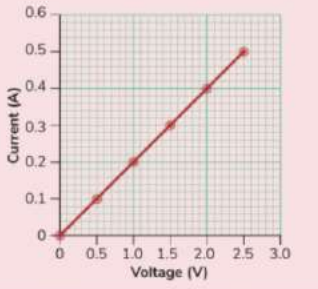
This straight line tells us several important things:
- The voltage across the resistor increases as the current flowing through it increases.
- If the voltage is doubled, the current is also doubled.
- The voltage is directly proportional to the current. This means voltage and current increase together in the same ratio.
- The straight line through the origin confirms Ohm's Law.
Using the graph to find resistance
The graph can also be used as a source of information to calculate resistance.
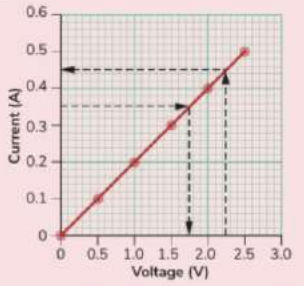
To find the resistance of the wire:
- Choose any value of voltage on the graph and draw a horizontal dashed line to the graph line.
- From this point, draw a vertical dashed line down to find the corresponding current.
- Insert these values into the equation:
- Calculate the resistance.
Worked Example: Finding Resistance from a Graph
If at a voltage of V, the current flowing is A, then:
This means the resistance of the wire is 5 ohms.
Electronic Components
Electronic components are special devices that can be used to build more complex circuits. Each component has a specific function and behaves differently from a simple resistor. Understanding how these components work helps you design circuits for different purposes.
The Diode
A diode is an electronic component that allows current to flow through it in only one direction.
How diodes work
Diodes behave like one-way gates for electrical current:
- When the diode is connected in forward bias (positive side to positive, negative side to negative), current can flow through it.
- When the diode is connected in reverse bias (connections reversed), the diode blocks the current and very little or no current flows.
- Diodes only allow small currents to flow through them. If a large current tries to flow, the diode will be damaged.
Diodes need to be protected by connecting resistors in series with them to prevent damage from excessive current.
Circuit symbol and polarity
The circuit symbol for a diode shows which way current can flow:
- The symbol consists of a triangle pointing to a line.
- The triangle points in the direction that current can flow.
- The thick black line represents the negative side of the diode.
- The triangular arrow represents the positive side.
- It is very important to connect the negative side of the diode to the negative side of the battery. This allows current to flow through the diode.
Exam Tip: When identifying a diode in an exam, you need to be able to recognise it by its circuit symbol. Remember that the thick black line is the negative side and that the arrow shows the direction current flows.
Investigating diode operation
To understand how a diode works, you can set up a simple experiment with a battery, bulb, and diode.
Experiment setup:
- Connect the negative side of the diode to the negative side of the battery. In this arrangement, the diode is in forward bias.
- Complete the circuit with a bulb.
- Observe that current flows through the diode and the bulb lights up.
- Now reverse the direction of the diode by connecting the positive side to the negative side of the battery. The diode is now in reverse bias.
- Observe that current does not flow through the diode and the bulb does not light up.
This experiment demonstrates the one-way property of diodes - they only allow current to flow in one direction.
Light-Emitting Diode (LED)
A light-emitting diode (LED) is a special type of diode that emits light when current flows through it.

How LEDs work
LEDs have some important characteristics:
- Since an LED is a type of diode, it will only allow current to flow in one direction.
- When current flows through the LED in the correct direction (forward bias), it acts like a bulb and emits light.
- If you look at an LED closely, you will notice that one leg is shorter than the other. The shorter leg should be connected to the negative side of the battery in a circuit.
- The longer leg connects to the positive side of the battery.
Memory Aid: Remember LED = Light Emitting Diode - it gives off light when electricity flows through it correctly!
Using LEDs safely
In modern electronic devices, LEDs are used to replace traditional light bulbs because they use very little energy. They do not waste energy as heat and can remain lit for thousands of hours without burning out.
It is necessary to protect LEDs with a protective resistor to make sure that only a small current flows through the diode. Without this protective resistor, too much current would flow and the LED would be damaged.
Investigating LED operation
To investigate how an LED works, you can conduct an experiment similar to the diode experiment.
Experiment procedure:
- The positive leg of the LED is connected to the positive side of the battery. This puts the LED in forward bias and it will light up.
- Connect the negative side of the LED to the negative side of the battery to complete the circuit.
- When the circuit is completed correctly, the LED will emit light.
- If you reverse the connections so that the negative side of the LED connects to the positive side of the battery (reverse bias), the LED will not light up because current cannot flow through it in this direction.
This investigation shows that LEDs only work when connected correctly in a circuit.
Light-Dependent Resistor (LDR)
A light-dependent resistor (LDR) is a type of variable resistor that changes its resistance dramatically in response to light.
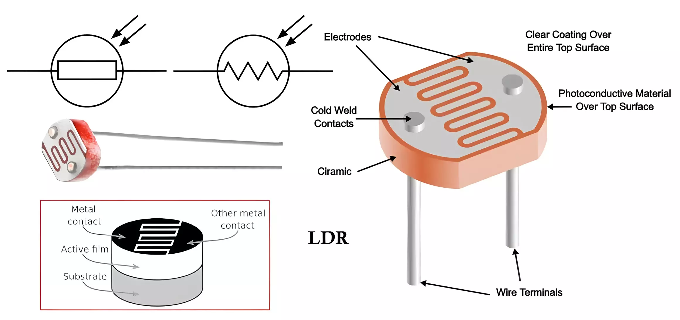
How LDRs work
The resistance of an LDR depends on the amount of light shining on it:
When light shines on an LDR, its resistance decreases. In darkness, the LDR has very high resistance. The brighter the light, the lower the resistance becomes.
Memory Aid: LDR = Light Dependent Resistor - its resistance depends on the amount of light!
Applications of LDRs
LDRs are used in many practical applications:
- If an LDR is connected in series with a battery and buzzer, it can act as a light-sensitive switch. The amount of current flowing depends on the amount of light shining on the LDR.
- LDRs are used in light meters in cameras to measure light levels.
- They are used to turn on street lights automatically when it gets dark.
- They can be part of more complicated circuits to control when lights turn on and off.
Investigating LDR operation
To investigate how an LDR responds to light, you can set up a circuit with a buzzer.
Experiment setup:
- A circuit is set up with an LDR connected in series with a buzzer and battery.
- When light shines on the LDR, its resistance drops, allowing current to flow through the circuit.
- The buzzer sounds when light shines on the LDR.
- When the LDR is covered or placed in darkness, its resistance increases dramatically, stopping current from flowing.
- The buzzer stops when the LDR is in darkness.
This investigation demonstrates how LDRs can be used as light-sensitive switches in electronic circuits.
The Thermistor
A thermistor is a device made of material whose resistance decreases significantly when its temperature increases.

How thermistors work
When the thermistor is heated, its resistance reduces dramatically, allowing current to flow more easily. At low temperatures, the thermistor has high resistance. The hotter it gets, the lower its resistance becomes.
Memory Aid: Thermistor = Thermal resistor - its resistance depends on temperature!
Applications of thermistors
Thermistors are used as temperature sensors in many applications:
- If a thermistor is connected in series with a battery, it can control the amount of current flowing in a circuit depending on the temperature.
- Thermistors are used in fire alarms to detect high temperatures.
- They are used in ovens and fridges as temperature sensors.
- They can be found in central heating thermostats.
Investigating thermistor operation
To investigate how a thermistor responds to temperature changes, you can set up a circuit with a buzzer.
Experiment procedure:
- A circuit is set up with a thermistor connected in series with a buzzer and battery.
- When the thermistor is heated, its resistance decreases. This allows current to flow through the circuit.
- The buzzer will sound when the thermistor is heated because current can flow through the circuit and the thermistor's resistance has decreased.
- When the thermistor cools down, its resistance increases again, reducing the current flow.
- The buzzer stops as the thermistor cools and its resistance increases.
This investigation shows how thermistors can be used to detect temperature changes in electronic circuits.
Electrical Power
Power is the rate at which work is done. In electrical terms, it measures how quickly electrical energy is converted from one form to another.
Understanding electrical power
When we talk about electrical power, we are describing:
- The amount of energy converted from electrical energy to another form in one second.
- All new electrical appliances come with a label that tells you the power rating of the appliance.
- The power of an electrical appliance is measured in watts (W), named after the Scottish scientist James Watt.
The power formula
Electrical power can be calculated using voltage and current:
where:
- = power in watts (W)
- = voltage in volts (V)
- = current in amps (A)
This formula tells us that the greater the voltage or current, the more power an appliance uses.
Memory Aid: Remember the "PIV" triangle for power calculations. Place P at the top, with V and I at the bottom. This helps you remember:
Understanding power ratings
A heater with a power rating of W (or kW) converts 2000 joules of electrical energy to heat energy in second. The power rating tells you:
- The rate at which the appliance converts energy (higher power = faster conversion)
- How much energy the appliance uses (higher power = more energy consumption and higher electricity costs)
Measuring power
The power rating of electrical appliances can be measured using a special device:
- A wattmeter is an instrument that measures electrical power in watts.
- One of the functions of a wattmeter is to act as a plug-in energy-saving monitor.
- This can be useful to check the energy use of appliances when in use or in stand-by mode.
- Many school labs are equipped with wattmeters, which can measure the electrical power of laboratory circuits.
Calculating Electrical Power
You can calculate the power of an electrical appliance if you know the voltage and current.
Worked Example: Calculating Power
Question: An electric kettle is connected to the V mains power supply. The kettle draws a current of A. Calculate the power of the kettle.
Solution:
- Step 1: Write the formula: power = voltage × current
- Step 2: Fill in the values: power =
- Step 3: Write the answer with the correct unit: power = W (or kW)
Answer: The power of the kettle is 2300 watts or 2.3 kilowatts.
Key points about power calculations
- Always remember that watts equals volts times amps.
- When performing calculations on electrical power, you must use the correct formula and units.
- Power is measured in watts (W), but kilowatts (kW) are often used for high-power appliances ( kW = W).
- The formula can be rearranged to find voltage or current if you know the power:
- To find voltage:
- To find current:
Exam Tip: Remember that watts equals volts times amperes. Make sure you use the correct units in your calculations and always show your working clearly.
Key Points to Remember:
-
Ohm's Law states that voltage is proportional to current in a wire at constant temperature. The formula is .
-
Voltage, current, and resistance are related by the equation , where voltage is measured in volts (V), current in amps (A), and resistance in ohms (Ω).
-
A diode allows current to flow in only one direction. A light-emitting diode (LED) is a type of bulb that emits light when current flows through it.
-
The power of an electrical appliance is a measure of the amount of electrical energy converted to another form each second. It can be calculated using the formula and is measured in watts (W).
-
Electronic components like LDRs and thermistors are variable resistors whose resistance changes with light and temperature respectively. These can be used to create sensors and automatic switches.
-
LDR resistance decreases when light shines on it, while thermistor resistance decreases when temperature increases.
-
Always protect diodes and LEDs with resistors in series to prevent damage from excessive current.