Current Electricity (Junior Cert Science): Revision Notes
Current Electricity
Introduction to electricity
Electricity is a fundamental part of modern life, powering everything from light bulbs to smartphones. Understanding how electric current works is essential for anyone studying physics or engineering.
Scientists have been studying electricity for over 400 years, and this chapter explores the basic principles of how electric current works in circuits and electrical devices.
Basic electrical circuits
How to get a bulb to light
To make a bulb light up, you need to create a complete electrical pathway. This requires:
- A battery (or cell) to provide energy
- A bulb to convert electrical energy into light
- Wires to connect the components
- A continuous metal loop so electricity can flow
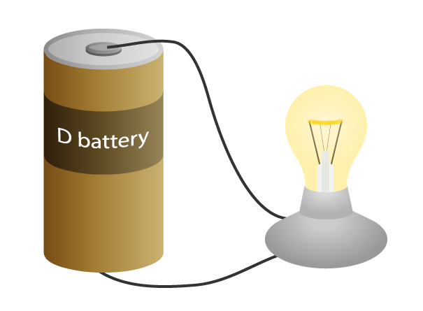
When each terminal of a battery is properly connected with wires to the bulb, electricity flows through the circuit and the bulb lights up. The word circuit comes from a Latin word meaning "to go around".
What is an electrical circuit?
A complete path is essential for electricity to flow. If there is any break in the circuit, electricity cannot flow and devices will not work.
We call this complete path an electrical circuit.
Definition: An electrical circuit is a continuous loop of metal that allows electricity to flow through it.
This is why a switch is useful - it creates or breaks the connection, allowing you to control when electricity flows.

What is flowing in the wires?
When electricity flows through a wire, it is actually individual electrons that are moving. These tiny charged particles travel through the metal.
Definition: Electric current is a flow of electrons.
How a Bulb Produces Light
Here's what happens inside a circuit when a bulb lights up:
- Electrons are released from the negative side of the battery
- They travel through the metal wires
- Eventually, the electrons pass through the circuit and re-enter the battery at the positive side
- When electrons are forced to move through a thin wire (called a filament in a bulb), the wire resists their motion
- This resistance causes the filament to heat up
- When it gets hot enough, the filament glows white and produces light
This movement of electrons around a circuit is called electric current.
Conductors and insulators
Not all materials allow electricity to flow through them equally well.
Conductors are substances that allow electricity to travel through them easily. Metals like copper, iron, and aluminium are good conductors.
Insulators are substances that do not allow electricity to travel through them. Plastic, rubber, and wood are examples of insulators.
Experiment 34.1: Classifying materials as conductors or insulators
This experiment helps you determine whether different materials conduct electricity.
Experiment: Testing Conductors and Insulators
Procedure:
- Set up a circuit with a battery and a bulb
- Connect two crocodile clips to the circuit, leaving a gap between them
- First, connect the crocodile clips together to test that the circuit works (the bulb should light)
- Now place different materials between the crocodile clips
- Observe whether the bulb lights up or not
Results:
- If the bulb lights when a material is inserted, that material is a conductor
- If the bulb remains unlit, the material is an insulator
This simple test allows you to classify a wide range of materials based on their electrical properties.
Circuit diagrams
Why use symbols?
Drawing detailed pictures of every component in a circuit would be time-consuming and difficult. Instead, scientists and engineers use standard symbols to represent components. This makes circuit diagrams quick to draw and easy to understand internationally.
Common circuit components
Here are some symbols used for common electrical components.
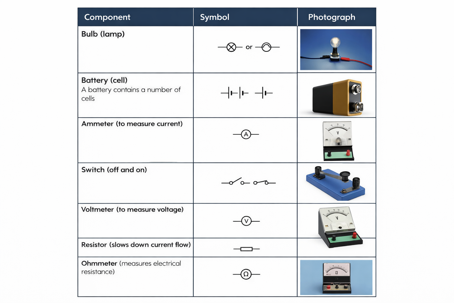
| Component | Symbol | Purpose |
|---|---|---|
| Bulb (lamp) | Circle with X inside | Converts electrical energy to light |
| Battery (cell) | Long and short parallel lines | Provides electrical energy |
| Ammeter | Circle with A inside | Measures current |
| Switch | Break in line with gap | Controls whether circuit is on or off |
| Voltmeter | Circle with V inside | Measures voltage |
| Resistor | Rectangle or zigzag line | Resists current flow |
| Ohmmeter | Circle with Ω inside | Measures resistance |
Exam Tip: You need to be able to recognise these symbols and know what each component does. These symbols appear on the State Examinations Commission Formula and Tables booklet.
Reading circuit diagrams
Circuit diagrams show how components are connected together. Lines represent wires, and symbols show the components. Following the lines around shows you the complete path that electricity would take if the switch was closed.
Measuring current
What is electric current?
As we learned earlier, electric current is the flow of electrons through a wire. But how do we measure how much current is flowing?
The ammeter
To measure the amount of current flowing in a circuit, we use a device called an ammeter.
Definition: An ammeter measures the current flowing in a circuit.
The ammeter must be placed directly in the path of the current - we say it is connected in series with the components. This means the current must flow through the ammeter.
The ampere
Current is measured in units called amperes, usually shortened to amps or represented by the symbol A.
The unit is named after André-Marie Ampère, a French physicist and mathematician who invented the solenoid and was one of the founders of electromagnetism.
As the current passes through the ammeter, it measures the number of electrons passing through per second. The more electrons flowing, the higher the current reading in amps.
Experiment 34.2: Measuring current in a circuit using an ammeter
This experiment demonstrates how to correctly connect an ammeter to measure current.
Experiment: Measuring Current with an Ammeter
Procedure:
- Make a circuit with a switch and a bulb to ensure the bulb is working
- Remove a wire from one side of the bulb
- Connect an ammeter into the circuit in series
- Break the circuit at any point and add an ammeter in series at different positions
Results:
When you measure the current at different points in a series circuit, you find that the ammeter gives the same reading everywhere. This shows that in a series circuit, the current is the same throughout.
Series and parallel circuits
Bulbs in series
In a series circuit, components are connected one after another in a single loop. The electrons that pass through one bulb must also pass through the second bulb.
Important Points About Series Circuits:
- The same amount of current flows through each part of the circuit
- Each ammeter placed in the circuit gives the same reading
- If one bulb is removed or blows, the circuit is broken and all bulbs go out
- This is like old-fashioned Christmas tree lights - when one bulb blew, the whole string went out
Bulbs in parallel
In a parallel circuit, the current from the battery can split and take different pathways. Some current can enter one bulb while the remainder enters another bulb.
Key Features of Parallel Circuits:
- If one bulb is disconnected or blows, the second bulb can remain lit
- Each bulb has an independent pathway for current to flow
- The bulbs are connected in parallel
- This ensures that if one bulb blows, the other bulbs will remain lit
- This is the same principle used in house lighting - if one light blows, the others stay on
- Modern car headlights also use parallel circuits
The current coming from the battery splits between the different branches. If one bulb blows, current can still flow through the other branch.
Voltage and potential difference
What causes current to flow in a circuit?
For electrons to move through a wire, they must be given energy. This energy comes from the battery.
You might like to think of a battery as an "electron pump". The pushing power of a battery is measured in units called volts, and we use the term voltage or potential difference to describe this.
Definition: Potential difference is measured with a voltmeter. The unit is the volt (V).
The voltage (or potential difference) is always measured between two points. It's important to realise that potential difference is measured in volts using a voltmeter.
The battery
The energy to push the electrons comes from chemical energy stored in the battery.
Alessandro Volta was an Italian scientist who invented the first battery using discs of copper and zinc soaked in sulphuric acid. This was the first source of steady electric current. The unit of potential difference (the volt) is named in his honour.
Measuring voltage
A voltmeter is used to measure the voltage (potential difference) between two points in a circuit.
Unlike an ammeter (which must be in series), a voltmeter is always connected in parallel with the component you want to measure across. This means it is connected across the two ends of a component.
Battery polarity
Batteries have two terminals - a positive terminal and a negative terminal. It's important to identify these correctly.
- The wire connected to the long thin line in the circuit symbol is the positive side
- The wire connected to the shorter, thicker line is the negative side
Safety Note: You do not need to worry about getting a shock from a low voltage (anything under 30 volts). However, you should still handle batteries carefully.
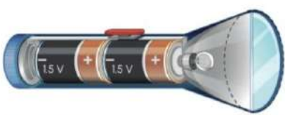
The diagram shows how batteries are arranged inside a torch. Two 1.5 V batteries are connected in series, giving a combined voltage of 3.0 V to power the bulb.
Experiment 34.3: Measuring voltage and current in the same circuit
This experiment shows you how to measure both voltage and current in a single circuit.
Experiment: Measuring Voltage and Current Together
Procedure:
- Set up a circuit with a bulb to ensure that the bulb is working
- To measure the current flowing through the bulb, break the circuit at any point and add an ammeter in series
- To measure the voltage across the bulb, place a voltmeter in parallel with the bulb
Results:
You can measure both the current (in amps) and the voltage (in volts) in the same circuit. The ammeter shows current flow, while the voltmeter shows the potential difference across the bulb.
Exam Tip: In your exam, you may be shown a circuit that you have not seen before. You may be told some information about changing voltage and resistance, and you may be asked to predict what will happen. It is important that you understand the effect of changing resistance and voltage on current flow.
Resistance
What is resistance?
When a bulb is connected to a battery, the electrons entering the bulb must flow through a very thin wire called the filament.
Since the electrons are forced to move through this thin wire, they experience resistance. Two important things happen:
- The motion of the electrons is slowed down (this is called resistance)
- As they try to flow through the resistor, the resistor itself gets warm or even hot
In a bulb, the filament wire is so hot that it glows white, producing light. The filament wire is said to behave as a resistor.
Definition: A resistor is a component that slows down the flow of electric current.
Measuring resistance
Resistance is measured using an instrument called an ohmmeter.
Definition: The unit of resistance is the ohm, represented by the symbol Ω.
The relationship between voltage, current and resistance
There is an important relationship between these three quantities:
- For a fixed voltage: the greater the resistance in the circuit, the lesser the current
- For a fixed resistance: the greater the voltage in a circuit, the greater the current
Think about it this way: resistance opposes current flow, so more resistance means less current can flow. However, increasing the voltage (the push) can force more current through the same resistance.
Experiment 34.4: Measuring the resistance of an object
This experiment shows you how to use an ohmmeter to measure resistance.
Experiment: Using an Ohmmeter
Procedure:
- Switch on the ohmmeter (your teacher will tell you what setting to use)
- Connect the object whose resistance needs to be measured between the black and red leads
Results:
The ohmmeter displays the resistance reading. The unit shown is the ohm (Ω). A circuit diagram showing an ohmmeter connected to measure an object's resistance is also provided.
Types of resistors
There are several different types of resistors used in circuits, each with different properties.
Fixed and variable resistors
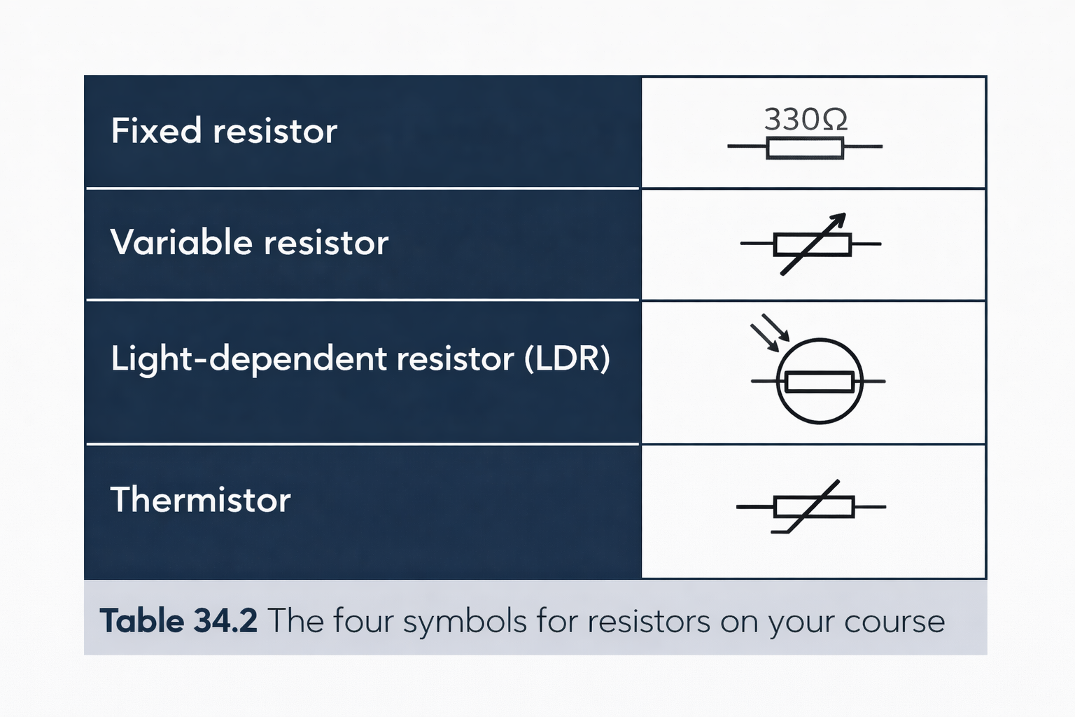
Fixed Resistors
Fixed resistors have one value for resistance. They are represented in a circuit diagram by a rectangular symbol or zigzag line. The resistance value is often written on the resistor itself. For example, a 330 Ω resistor always has a resistance of 330 ohms.
Variable Resistors
Variable resistors are usually represented by a rectangular symbol with an arrow crossing diagonally. Their resistance can be changed by moving a sliding contact. This allows you to control the current in a circuit - useful for things like volume controls or dimmer switches.
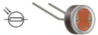
Light-dependent resistor (LDR)
One type of variable resistor is the light-dependent resistor or LDR. The resistance of an LDR changes when light shines on it.
- When light shines on an LDR, its resistance decreases
- The symbol for an LDR shows a resistor symbol inside a circle with arrows pointing towards it (representing incoming light)
LDRs are used in circuits for automatic outdoor lights or light meters in cameras.
Thermistor
Another type of variable resistor is the thermistor. The resistance of a thermistor changes when its temperature is changed.
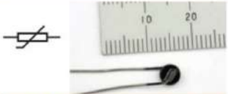
When a thermistor is heated, the resistance changes with temperature.
Thermistors can be used to make circuits that respond to temperature changes, such as thermostats or temperature sensors.
Experiment 34.5: Investigating the resistance of a variable resistor
This experiment demonstrates how a variable resistor (rheostat) works.
Experiment: Variable Resistor Investigation
Procedure:
- Switch on the ohmmeter and connect it to terminals A and C of the variable resistor
- Read the resistance
- When the sliding contact of the variable resistor is moved, the resistance changes
- Repeat the experiment by connecting the ohmmeter to terminals B and C
- Note that the resistance does not change because you are not varying the resistance
Application:
A circuit diagram shows a practical application. A variable resistor is used to control the current in a bulb circuit. Varying the resistance controls how brightly the bulb glows.
Results:
By adjusting the sliding contact, you can change the resistance between certain terminals. This allows you to control the amount of current flowing through a circuit.
Understanding circuits using models
A water pump model to represent voltage
To get a clearer picture of how current, voltage and resistance are related, an electrical circuit can be compared to a water pump that is pumping water around a loop of pipe.
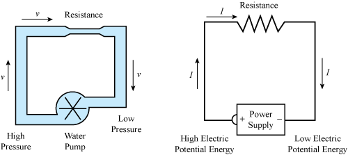
The Water Pump Analogy
In this model:
- The pump represents the battery (it provides the push)
- The water current represents the electric current (the flow)
- A narrow section of pipe would represent resistance (it restricts the flow)
Think about these comparisons:
- The more powerful the pump, the greater the quantity of water pumped around the circuit per second
- Similarly, the greater the voltage of the battery, the greater the number of electrons that are pushed around the circuit per second
- If you stood next to any part of the circuit and could see the electrons passing you, a lot more electrons will pass when the powerful pump is used than when the weaker pump is used
- In short, when the resistance is constant, then the greater the voltage, the greater the current
Now imagine the pipe has a narrow section:
- Resistance can be thought of as a narrowing in part of a circuit, as a narrower pipe offers less water flow around the circuit every second
- Similarly, in an electrical circuit, inserting a resistor can be compared to narrowing a pipe in part of a circuit
- The narrower the pipe, the less water is circulating in one second
- Similarly, the greater the value of the electrical resistance in an electrical circuit, the less current flows in it
- Therefore, the greater the resistance in the circuit, the lower the current flows
This water model helps us understand the relationships between voltage (the push), current (the flow), and resistance (the restriction).
Remember!
Key Points to Remember:
-
Electric current is a flow of electrons. The amount of current flowing in a circuit is measured using an ammeter. Ammeters are always connected in series in a circuit. The unit of current is the ampere (A).
-
When bulbs are connected in series, the same current flows in both bulbs. If one bulb blows, the other will also stop glowing.
-
When bulbs are connected in parallel, each bulb has an independent pathway for current to flow. If one bulb blows, the second can stay lit.
-
Another name for voltage is potential difference. The voltage (potential difference) between two points is measured using a voltmeter. Voltmeters are always connected in parallel. The unit of voltage is the volt (V).
-
Resistance of an object is a measure of the opposition it has to the flow of electric current. Resistance is measured using an ohmmeter. The unit of resistance is the ohm (Ω).
-
The resistance of a variable resistor can be changed. The resistance of a light-dependent resistor (LDR) is changed when light shines on it. The resistance of a thermistor is changed when its temperature is changed.