Isometric Drawings (Leaving Cert DCG): Revision Notes
Isometric Drawings
What are isometric drawings?
Isometric drawings are a type of pictorial projection that shows objects in three dimensions. Unlike orthographic projections which show separate views, isometric drawings present a single 3D view that reveals three faces of an object simultaneously. This makes them particularly useful for showing the overall shape and form of objects more clearly than traditional technical drawings.

Isometric drawings bridge the gap between flat technical drawings and complex 3D models, making them invaluable for communication between designers, engineers, and manufacturers.
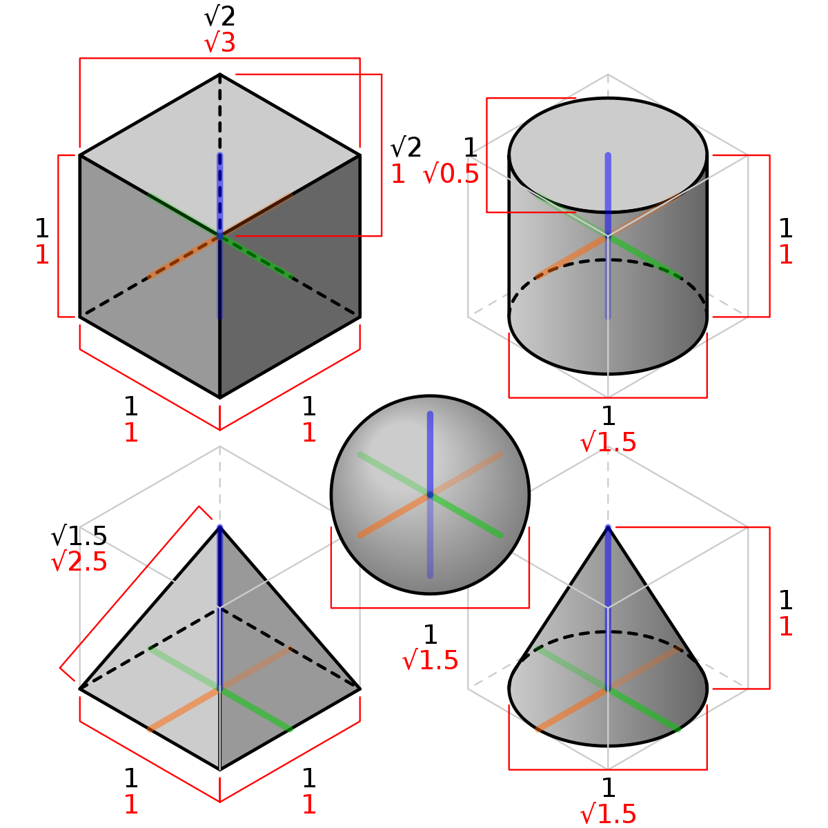
The key characteristic of isometric drawings is that they use specific angles to create the 3D effect. However, there are important limitations to understand:
- Measurements are only accurate along isometric axes - you can only measure true lengths along lines that run parallel to the main isometric directions
- Angles appear distorted - no angles show their true size in isometric views
- Circles become ellipses - any circular features will appear as elliptical shapes
- Primarily used for illustration - these drawings are excellent for showing how something looks, but less suitable for precise manufacturing
Understanding these limitations is crucial for correctly interpreting and creating isometric drawings. Never assume that what you see in an isometric view represents true measurements or angles.
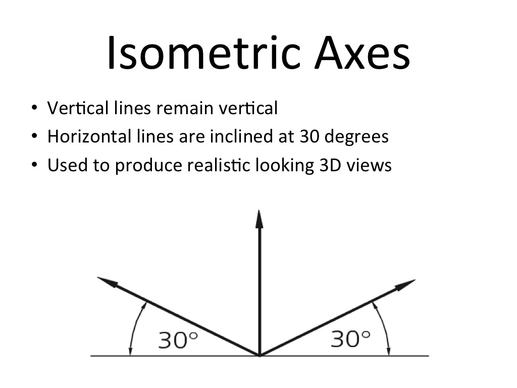
The isometric axis system
The foundation of all isometric drawing is the axis system. This consists of three main directions that represent the length, width, and height of objects:
- Left-hand axis - slopes down at 30 degrees to the horizontal (represents width)
- Right-hand axis - slopes down at 30 degrees to the horizontal (represents length)
- Vertical axis - remains completely vertical (represents height)
This 30-degree system creates the characteristic appearance of isometric drawings where objects appear to be viewed from slightly above and to one side.
The 30-degree angles are what give isometric drawings their distinctive look and ensure that all three faces of an object are visible and equally emphasised.
Basic construction steps
Creating an isometric drawing from orthographic views follows a systematic process. You start with the traditional elevation and plan views, then transfer the key measurements to your isometric axes.
The construction process involves setting up your isometric axes first, then carefully measuring distances from your orthographic views and transferring these measurements along the appropriate isometric directions. You build up the drawing step by step, typically starting with the basic rectangular outline and then adding details and features.
Working systematically is essential for accuracy. Always establish your framework before adding details, and remember that precision in the early stages will save time and reduce errors later.
The yellow-coloured examples in the technical diagrams show how a simple rectangular block progresses from basic axis lines through to a complete three-dimensional representation.
Drawing sloping lines and surfaces
One of the most important concepts in isometric drawing is understanding how sloping lines behave. This is crucial because many real objects contain sloped surfaces, angled cuts, or inclined features.
Key principle: Sloping lines do not maintain their true length in isometric drawings, and angles do not show at their true size. This means you cannot simply measure an angle from your orthographic view and apply it directly to your isometric drawing.
Solution method: Convert angular measurements into linear measurements along the isometric axes. Instead of working with angles, you work out the horizontal and vertical distances that create the slope, then transfer these distances along your isometric axes.
Worked Example: Drawing a Triangular End
Instead of measuring the angled sides directly from your orthographic view:
- Identify key corner points of the triangle
- Measure the horizontal and vertical distances to each point
- Transfer these distances along the isometric axes
- Connect the plotted points to create the sloped lines
This method ensures accuracy because you're working with measurements that can be properly transferred to isometric projection.
Drawing circles in isometric
Circles present a particular challenge in isometric drawing because they always appear as ellipses. The shape and orientation of these ellipses depends on which face of the object the circle appears on. There are several methods for drawing these elliptical shapes, each with different levels of accuracy and complexity.
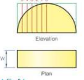
Coordinate method
This is the most accurate method for drawing circles in isometric views. The technique involves dividing the original circle into a grid system and then transferring coordinate points to create the elliptical curve.
Process overview:
- Divide the circle in the orthographic view using a coordinate grid
- Transfer each coordinate point to the isometric view
- Plot these points along the isometric axes
- Connect the points with a smooth curve to form the ellipse
The coordinate method produces very accurate results because you can plot as many points as needed. However, it requires more time and careful measurement compared to approximate methods.
Four-centre ellipse method
For most isometric drawings, an approximate ellipse is perfectly satisfactory since these drawings are primarily used for illustration rather than precise measurement. The four-centre ellipse method provides a quick way to construct ellipses using only a compass and straightedge.
Key advantages:
- Much faster than the coordinate method
- Requires only basic drafting tools
- Provides sufficient accuracy for most purposes
- Easy to construct once you learn the technique
Construction principle: The method uses four different compass centres to create four arc segments that combine to form an ellipse-like shape. While not mathematically perfect, this approximation is close enough for practical purposes.
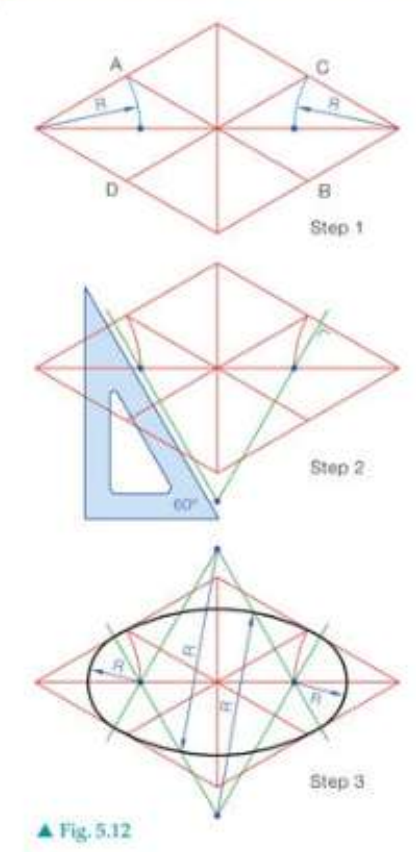
The construction involves creating a diamond framework first, then using specific geometric relationships to locate the four centres needed for the compass arcs.
Ortho four-centre ellipse
This is a variation of the standard four-centre ellipse method that provides an alternative construction approach. The ortho four-centre method can be particularly useful when dealing with circles that appear on different faces of isometric objects.
Construction steps:
- Draw a square framework around the circle position
- Use geometric construction to find the four compass centres
- Draw perpendicular lines through specific points
- Locate centres for the arc segments
- Complete the ellipse using compass arcs
The method produces similar results to the standard four-centre approach but may be more suitable for certain situations or personal preferences in construction technique.
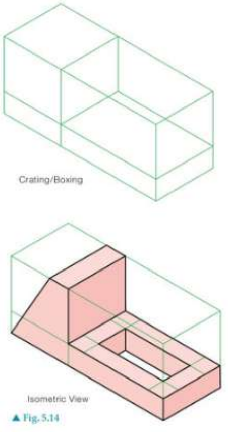
Crating or boxing method
The crating or boxing technique is an extremely useful method for simplifying the construction of complex objects in isometric projection. This approach is particularly valuable when dealing with objects that have irregular shapes or multiple features.
Basic concept: Instead of trying to draw complex shapes directly, you first construct simple rectangular boxes (crates) around the object or its major parts. These boxes are much easier to draw accurately in isometric, and they provide a framework for constructing the actual object details.
Process outline:
- Identify the overall dimensions of your object from orthographic views
- Draw rectangular boxes in isometric that will contain the object parts
- Use these boxes as construction guidelines
- Add the actual object details within the box framework
- Remove construction lines when complete
Benefits of crating:
- Makes complex objects much more manageable
- Helps ensure accurate proportions
- Provides reference points for positioning features
- Reduces errors in measurement transfer
Worked Example: Using the Crating Method
When drawing a complex mechanical part:
- Identify the main body dimensions from orthographic views
- Draw the main rectangular "crate" in isometric using these dimensions
- Add smaller crates for features like bosses, holes, or projections
- Use the crate edges as guides to draw the actual part details
- Erase construction lines to reveal the finished drawing
Think of it as building a scaffolding system that supports your drawing construction.
The technique is especially useful for mechanical parts, architectural elements, and any objects with multiple levels or stepped features.
Exam tips for isometric drawing
Essential Exam Strategies:
- Always set up your axes first - ensure the 30-degree angles are accurate
- Work systematically - don't try to draw everything at once
- Use light construction lines - you can darken the final outline later
- Check your measurements - only measure along isometric axes
- Remember circle behaviour - all circles become ellipses
- Consider using crating - it can save time on complex objects
- Practice different methods - be comfortable with both coordinate and four-centre ellipse techniques
Key Points to Remember:
- Isometric drawings use 30-degree axes to create 3D pictorial views that show three faces of an object simultaneously
- Angles and circles are distorted - angles don't show true size and all circles appear as ellipses in isometric projection
- Measurements are only accurate along isometric axes - you cannot measure true lengths on sloping lines or angled surfaces
- Multiple methods exist for circles - coordinate method is most accurate, four-centre ellipse is faster and sufficient for most purposes
- Crating technique simplifies complex objects - use rectangular boxes as construction frameworks to make difficult shapes more manageable