Worked Examples (Leaving Cert DCG): Revision Notes
Worked Examples
Example 1: Stepped object projection
This first worked example demonstrates how to create multiple views of a complex three-dimensional object using orthographic projection techniques. You'll learn to construct front elevation, end elevation, plan view, and isometric representations of the same object.

Understanding the problem
The task requires you to draw the front elevation, end elevation and plan of a stepped solid object. From these orthographic views, you must then produce an isometric view of the object. This type of question tests your ability to visualise a 3D form and represent it accurately in different projection systems.
Orthographic projection is the foundation for all technical drawing. Each view shows the object from a specific direction, revealing different features and dimensions that combine to give a complete understanding of the three-dimensional form.
Key construction steps
The orthographic views are drawn using specific dimensions and construction methods:
- Measurements: The object includes key dimensions
- Front elevation: Shows the object as viewed from the front, displaying the stepped profile
- End elevation: Reveals the side view, showing the depth and any features not visible from the front
- Plan view: Provides a bird's eye view from above, showing the object's footprint and internal features
Creating the isometric view
Once you've completed the orthographic projections, you can construct the isometric cube with lines. The isometric view combines information from all three orthographic views to create a realistic three-dimensional representation that shows three faces of the object simultaneously.
Critical Measuring Rule
Remember that measuring is only allowed in specific directions in isometric projection. You must transfer measurements from your orthographic views rather than scaling directly from the isometric construction.
Example 2: Regular pentagon with central portion
This second example focuses on constructing views of a regular pentagon shape, which presents unique challenges due to its five-sided geometry and internal construction requirements.
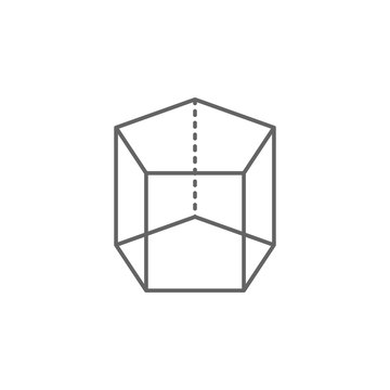
Problem overview
The exercise involves drawing the plan and elevation of a solid object featuring a regular pentagon shape. The pentagon contains a central portion that must be accurately constructed, and you need to show both the elevation view and plan view with proper construction lines.
Worked Example: Pentagon Construction Process
Creating a regular pentagon requires careful geometric construction:
Step 1: Draw the central portion elevation first Step 2: Construct the pentagon perimeter with equal sides Step 3: Add internal geometric divisions using construction lines Step 4: Use vertical ordinates to establish internal geometry
Drawing sequence
Start with the elevation view of the central portion, then construct the regular pentagon around it. The construction involves drawing the pentagon's perimeter first, then adding the internal geometric divisions. These vertical lines help define the internal structure of the solid.
Key measurements to remember:
- Pentagon sides are typically 45mm
- Internal features at 50mm intervals
Special considerations
When working with pentagon geometry, remember that the angles between sides are each. The internal construction requires careful measurement and the use of construction lines to ensure accuracy. The ordinates shown in the drawing help maintain proper proportions throughout the construction process.
Regular polygons like pentagons have specific geometric properties that must be maintained. The internal angles are a mathematical requirement that ensures the shape closes properly and maintains its regular form.
Isometric representation
The curved central portion must be constructed using ordinates as shown in the technical drawing. This ensures that the front face is doubly curved, creating a realistic three-dimensional appearance. The construction method involves transferring key points from the orthographic views to build up the isometric form systematically.
Key Points to Remember:
- Always start with orthographic views before attempting isometric projections
- Use construction lines to maintain accuracy and show your working method
- Transfer measurements carefully between different views - don't scale directly
- Regular polygons like pentagons require specific geometric construction techniques
- Keep your construction lines light but visible to demonstrate proper drafting technique