Circles and Curves in Perspective (Leaving Cert DCG): Revision Notes
Circles and Curves in Perspective
When drawing technical objects in perspective, you'll often need to represent circular shapes like cylinders, pipes, and rounded components. Understanding how circles behave in perspective projection is essential for creating realistic technical drawings.
Mastering circular shapes in perspective is fundamental to technical drawing, as most mechanical and architectural objects contain curved elements that must be accurately represented.
Understanding circles in perspective projection
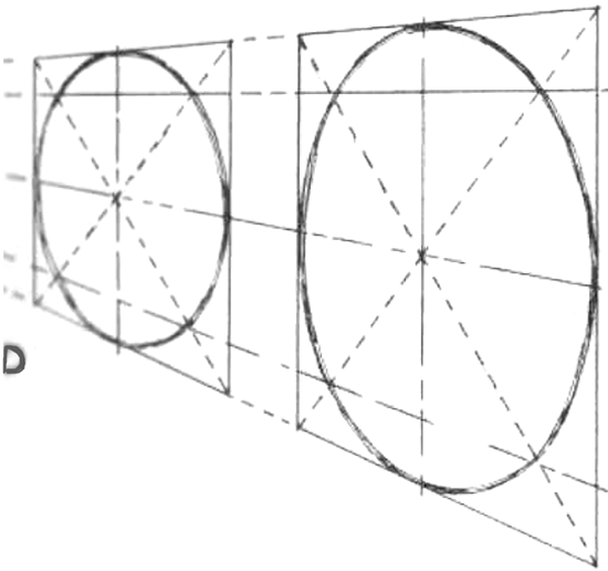
Key Principle: Circles change appearance depending on their relationship to the picture plane. When a circle is positioned parallel to the picture plane, it remains circular in the perspective view. However, when a circle is positioned at an angle to the picture plane, it transforms into an ellipse.
This transformation happens because perspective projection shows how objects appear to the human eye from a specific viewpoint. The further parts of the circle appear smaller, whilst the closer parts appear larger, creating the characteristic elliptical shape.
The division method for drawing circles in perspective
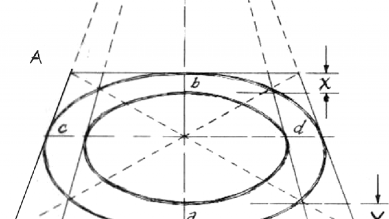
The most reliable technique for constructing accurate circular shapes in perspective is the division method using ordinates. This systematic approach ensures precision and helps maintain proper proportions.
The ordinate method is preferred by technical illustrators because it provides mathematical accuracy and can be applied consistently to any circular shape, regardless of its orientation or size in the perspective view.
Step-by-step process
The construction process follows these key stages:
Worked Example: Constructing a Circle in Perspective
Step 1 - Finding the height line: Begin by extending the front face of the cylinder until it intersects with the picture plane. This intersection creates your reference height line, which provides the basis for all subsequent measurements.
Step 2 - Establishing horizontal reference: From the height line intersection, draw a horizontal line across your drawing. This horizontal reference helps you determine the correct heights for each point in your perspective construction.
Step 3 - Dividing the elevation: In the elevation view (the side view showing the circular cross-section), divide the circle into equal segments using vertical ordinates. These division lines should be evenly spaced to ensure accuracy.
Step 4 - Applying divisions to the plan: Use the same ordinate divisions in your plan view. Each division line from the elevation must correspond to a matching division in the plan view.
Step 5 - Building the perspective: Using the ordinate method, project each point from both the plan and elevation views to construct the perspective shape point by point. Each ordinate provides one point on the final elliptical curve.
Key technical elements
Understanding the fundamental components shown in technical perspective drawings helps you construct accurate projections:
Essential Perspective Drawing Elements:
- Picture plane: The imaginary vertical surface onto which the perspective image is projected
- Horizon line: Represents the eye level of the observer and contains the vanishing points
- Ground line: The baseline where the ground plane meets the picture plane
- Vanishing points (VP1 and VP2): Points where parallel lines converge in two-point perspective
- Ordinates: Vertical division lines that help construct curved shapes systematically
Practical applications
This technique proves invaluable when drawing:
- Cylindrical components in machinery
- Pipes and tubes in technical installations
- Rounded architectural features
- Any circular cross-sections viewed at angles
The ordinate method ensures your circular elements integrate properly with the overall perspective construction, maintaining visual consistency throughout your technical drawing.

Remember that this systematic approach is not just about drawing circles – it's about maintaining visual consistency and mathematical accuracy throughout your entire technical perspective drawing.
Key Points to Remember:
- Circles parallel to the picture plane stay circular; circles at angles become ellipses
- The division method using ordinates provides the most accurate way to construct circles in perspective
- Always establish your height line first by finding where the object intersects the picture plane
- Divide both elevation and plan views equally for consistent results
- Build the perspective point by point using the ordinate projections
- This systematic approach ensures professional accuracy in your technical perspective drawings