Method of Constructing a one-point perspective (Leaving Cert DCG): Revision Notes
Method of Constructing a one-point perspective
One-point perspective is a fundamental drawing technique that allows you to create realistic 3D representations of objects on a 2D surface. This method is particularly useful in technical drawing and architectural representation, where objects appear to recede towards a single vanishing point on the horizon line.
Understanding the basic setup
Before beginning any one-point perspective construction, you need to understand the key elements that make this drawing system work. The construction relies on three primary reference lines and the strategic positioning of your viewpoint.
The picture plane acts as an imaginary transparent screen through which you view your object. Think of it as a window between you and the object you're drawing. The horizon line represents your eye level and contains the vanishing point where parallel lines appear to meet. The ground line establishes the base level from which all vertical measurements are taken.
These three reference lines - picture plane, horizon line, and ground line - form the foundation of your entire perspective construction. Understanding their relationship is crucial for accurate results.
Step-by-step construction method
Setting up your drawing space
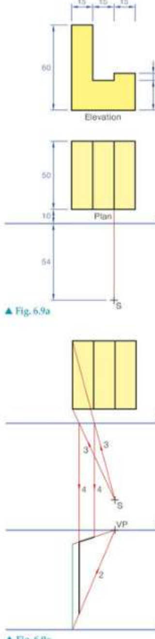
Begin by establishing your drawing area with the plan and elevation views of your object. Position these views so you have clear access to both the horizontal relationships (shown in plan) and the vertical relationships (shown in elevation). The spectator's position is crucial - this determines your viewing angle and affects how the perspective will appear.
Place the picture plane between the spectator and the object. The distance between the spectator and the picture plane influences how much of the object you can see and how dramatic the perspective effect will be.
The spectator's position relative to the picture plane is critical - it determines both your viewing angle and the dramatic effect of your perspective. Take time to consider this placement carefully.
Establishing the reference lines
Draw the ground line parallel to the picture plane. This line serves as your baseline for all height measurements and must be clearly marked.
Position the horizon line parallel to the ground line. The distance between these two lines represents the spectator's eye level above the ground. This spacing directly affects how you will view the object - whether you're looking up at it, down at it, or straight across.
Determining the vanishing point location
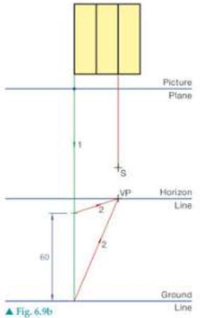
The vanishing point (VP) is located on the horizon line, directly in line with the spectator's position. This point is where all parallel lines that recede into the distance will appear to converge. Mark this point clearly as it will be used throughout your construction.
Using visual light rays for construction
Visual light rays are imaginary lines drawn from the spectator's eye to the corners and key points of your object. These rays help you determine where features of your object will appear in your perspective view.
Draw light rays from the spectator to each corner of the object as shown in the plan view. Where these rays pass through the picture plane, they establish the horizontal positions of these corners in your perspective drawing.
Visual light rays are your primary tool for transferring information from the plan view to the perspective view. Each ray tells you exactly where a feature will appear horizontally in your final drawing.
Building the elevation view
The elevation of your object is constructed using the height measurements from your original object. Since objects touching the picture plane maintain their true size, you can measure heights directly from your elevation view and transfer them to the perspective construction.
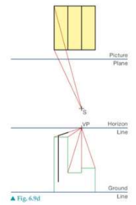
When objects extend behind the picture plane, their heights must be reduced proportionally. This is achieved by using the visual light rays to determine the correct proportions.
Completing the perspective view
The final perspective is created by finding where the visual light rays intersect with the height lines you've established. Each corner of your object in perspective view is located at the intersection of:
- A horizontal position determined by the visual light ray through the picture plane
- A vertical position determined by the height construction
Connect these intersection points to complete your one-point perspective drawing. All lines that were parallel to your line of sight in the original object will converge towards the vanishing point.
Key principles to remember
Objects that lie within the picture plane appear at their true size in the perspective view. This is why the picture plane is such a useful reference - anything touching it can be measured directly.
The further an object is from the picture plane, the smaller it appears in the perspective view. This scaling effect is controlled by the visual light rays and gives the drawing its sense of depth.
All horizontal lines that are parallel to your line of sight will converge at the vanishing point. Vertical lines remain vertical, and horizontal lines parallel to the picture plane remain horizontal.
Never forget that the picture plane is your measuring reference. Any distortion or scaling in your perspective drawing is relative to this plane. Objects touching the picture plane maintain their true proportions.
Key Points to Remember:
- The picture plane acts as your measuring reference - objects touching it show their true size
- The vanishing point is positioned on the horizon line directly in line with the spectator's position
- Visual light rays from the spectator determine the horizontal positions of object features in perspective
- Height measurements are taken from the elevation view and transferred to the perspective construction
- Objects further from the picture plane appear progressively smaller, creating the illusion of depth