Learning of Dimension (Leaving Cert DCG): Revision Notes
Learning of Dimension
When creating technical drawings, applying dimensions correctly is essential for clear communication. Proper dimensioning follows specific rules that ensure drawings are neat, legible, and professionally presented. These guidelines help maintain consistency across all technical documentation.
Dimension lines
Dimension lines are the foundation of technical drawing measurements. These lines appear as thin, dark, continuous marks that typically end with arrowheads. The primary purpose of dimension lines is to show both the direction and extent of a measurement on your drawing.
The arrowheads at each end point towards the object being measured. These arrows help clarify exactly which part of the drawing the dimension refers to. When drawing dimension lines, make sure they are evenly spaced and maintain consistent thickness throughout your drawing.
Maintaining consistent thickness and spacing across all dimension lines creates a professional appearance and ensures your technical drawings meet industry standards.
The spacing between dimension lines should remain uniform across the entire drawing. This creates a professional appearance and makes the dimensions easier to read and understand.
Extension lines
Extension lines work alongside dimension lines to show precisely where measurements apply. These are also thin, dark, solid lines that extend outward from the object you're dimensioning.
Critical Gap Requirement
Extension lines must maintain a gap of approximately 10mm between the object outline and where the extension line begins. This gap prevents confusion between the object's actual outline and the dimensioning information.
Extension lines should extend slightly beyond the dimension line, typically by about 3mm. This extension ensures the relationship between all dimensioning elements remains clear and visually balanced.

Placement of dimension lines and extension lines
Several fundamental rules govern the proper placement of dimensioning elements. Following these rules ensures your technical drawings maintain professional standards and communicate information effectively.
Rule 1: Shorter dimensions go closest to the object
Always place shorter dimensions nearer to the object being measured. Longer dimensions should be positioned further away. This hierarchy prevents dimension lines from crossing over each other unnecessarily.
Rule 2: Avoid crossing dimension lines
Dimension lines should never cross extension lines where possible. When dimensions must be placed outside the object, they should follow a logical sequence from shortest to longest as you move away from the object.
Rule 3: Group dimensions at the same level
When possible, dimensions should be grouped together at consistent levels. They should not vary significantly in height across the drawing, as this creates a cluttered and unprofessional appearance.
Dimensioning arcs and fillets
Curved features like arcs and circles require special dimensioning approaches. The centre of arcs and circles should be marked with a small cross, particularly when they are very small or unimportant features. The dimension should be placed as a radial measurement where practical.
For fillet radii that are similar in size throughout a drawing, it's more efficient to use a note rather than dimensioning each individual fillet.
Worked Example: Efficient Fillet Notation
Instead of dimensioning every fillet individually, use a comprehensive note:
"All fillet radii are 6 mm unless otherwise specified"
This approach saves space and reduces drawing clutter while maintaining clear communication.
Leaders
A leader is a thin, continuous line that connects notes or dimensions to specific features on your drawing. Leaders start from the note or dimension and end with either an arrow or a dot depending on what they're pointing to.
Leader Endings:
- Use an arrow when pointing to a surface or edge
- Use a dot when referring to a point or object outline
When a leader points to a surface or edge, it should end with an arrow. If the leader refers to a point or the outline of an object, it typically ends with a dot. Leaders should be drawn at angles that don't interfere with other drawing elements.
The leader line should be inclined and extend straight from the beginning or end of a note. If the leader refers to an arc or circle, it should point towards the centre of that feature for maximum clarity.
Chamfers and angles
Angles can be dimensioned using either coordinates or angular measurements. You can show angles by providing the angle value directly, or by giving both horizontal and vertical dimensions that define the angle through trigonometry.
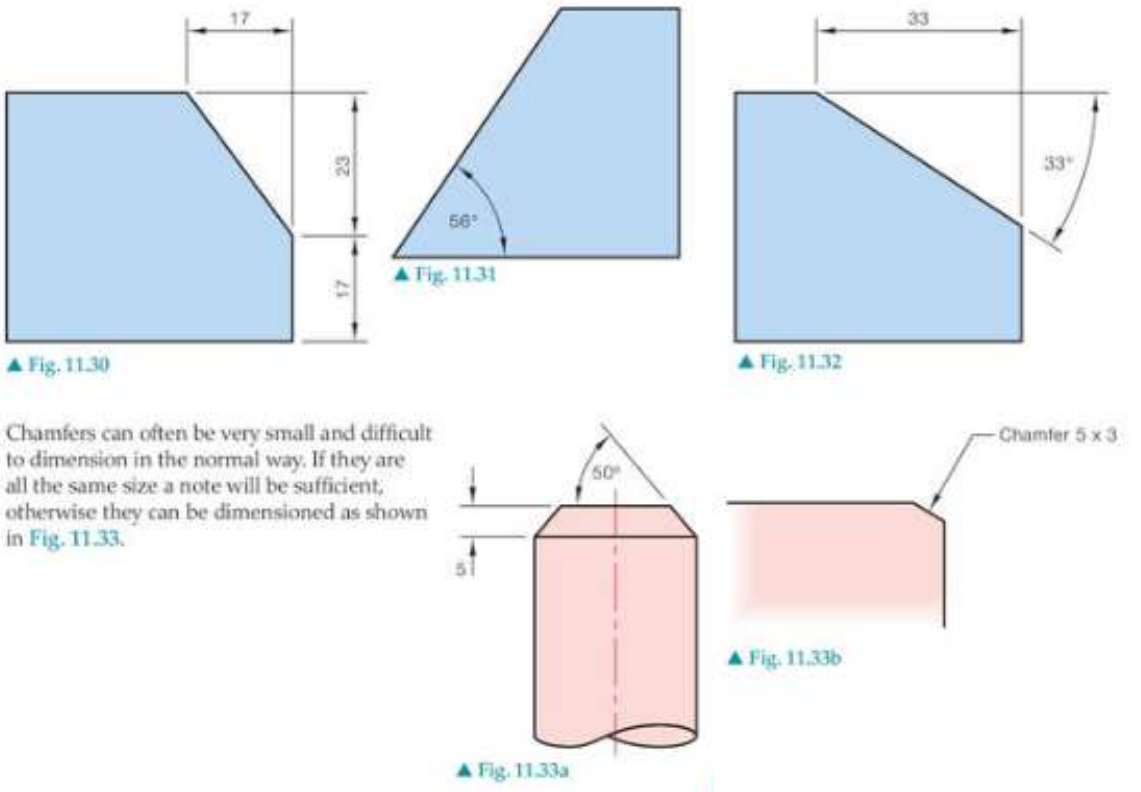
Chamfers are angled cuts that remove sharp edges from objects. Small chamfers that are difficult to dimension in the normal way can be shown using special notation.
Worked Example: Chamfer Notation
For small chamfers, use the notation format:
"Chamfer 5 x 3"
This indicates:
- 5 units wide
- 3 units deep
When chamfers are numerous and similar throughout a drawing, use leader lines pointing to representative examples with a note specifying that all similar chamfers follow the same specification.
When chamfers are very small and numerous throughout a drawing, they can be dimensioned using leader lines that point to representative examples, with a note indicating that all similar chamfers follow the same specification.
Remember!
Key Points to Remember:
- Dimension lines are thin, dark, solid lines with arrowheads that show measurement direction and extent
- Extension lines must have a 10mm gap from the object outline and extend 3mm beyond dimension lines
- Place shorter dimensions closer to the object and longer ones further away to avoid crossing lines
- Leaders connect notes to features using arrows for surfaces and dots for points
- Chamfers and angles can be dimensioned using coordinates, angular measurements, or special notation for small features