Symbols (Leaving Cert DCG): Revision Notes
Symbols
Technical drawing uses a standardised system of symbols to communicate design information clearly and efficiently. These symbols help save space on drawings whilst ensuring that all necessary information is communicated accurately to anyone reading the drawing.
What are symbols in technical drawing?
Symbols are standardised marks, lines, and shapes that represent specific information or instructions in technical drawings. Using symbols is common practice because they help to save both space on the drawing and time when creating drawings. Instead of writing out lengthy descriptions or creating complex illustrations, designers can use universally understood symbols that convey the same information quickly and clearly.
The universal nature of technical drawing symbols means that engineers and designers from different countries and backgrounds can interpret drawings accurately, making symbols an essential part of international technical communication.
Lines and linework
Good presentation in technical drawing requires consistent and appropriate linework. There must be consistency throughout the drawing regarding line tone and line thickness. Each line type serves a specific purpose and follows established conventions.
Maintaining consistent line weights throughout your entire drawing is crucial for professional presentation. Inconsistent linework can make drawings difficult to read and interpret correctly.
The main types of lines used in technical drawing include:
Thick continuous lines
These are the heaviest lines on a drawing and are used for:
- Visible outlines and edges
- Dimension and leader lines
- Hatching for sections
- Outlines of revolved parts
Thin continuous lines
These lighter lines serve multiple purposes:
- Dimensions and leader lines
- Hatching, fictitious outlines and edges
- Outlines of revolved parts
Short dashes
These broken lines indicate:
- Hidden outlines and edges
Chain lines
Chain lines consist of alternating long and short dashes and represent:
- Centre lines
- Extreme positions of moveable parts
Chain line thickened at ends and at changes in direction
This variation of chain lines is used for:
- Cutting/section planes
Wavy continuous lines
These undulating lines show:
- Limits of partial views or sections
Each line type has been carefully standardised to ensure consistent interpretation across all technical drawings. Learning to recognise and apply these line types correctly is fundamental to technical drawing competency.
First and third-angle projection symbols
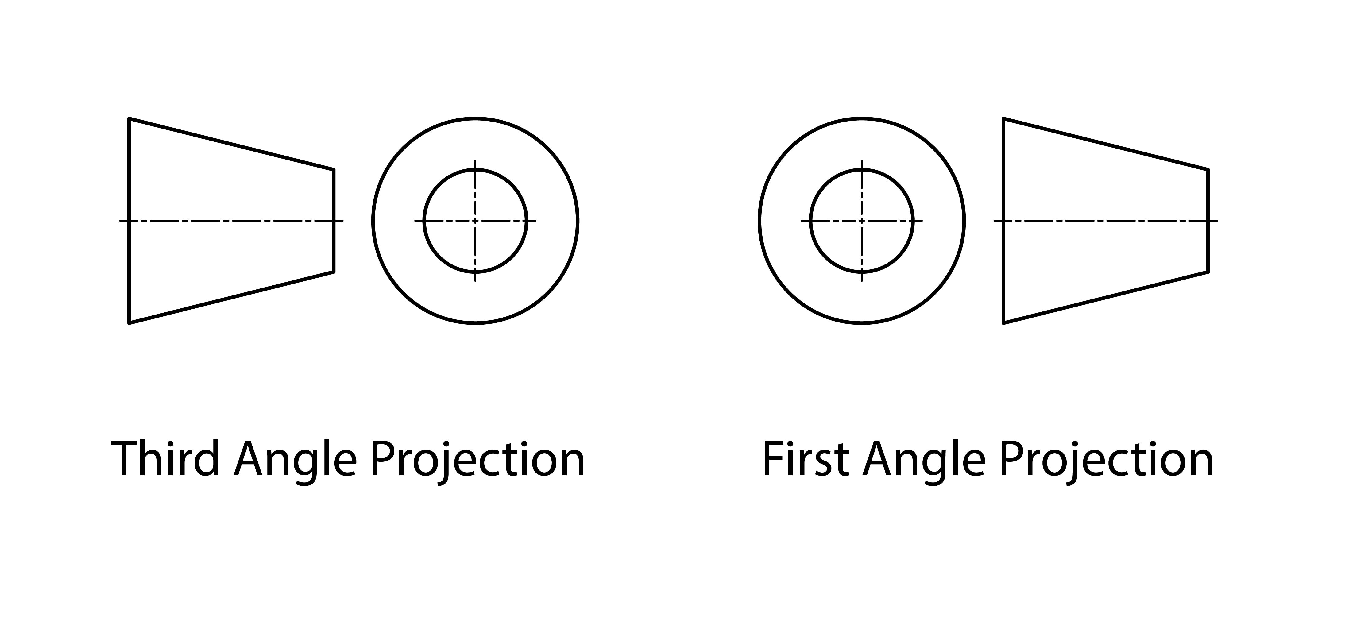
Understanding projection symbols is essential for interpreting technical drawings correctly. These symbols tell you which projection method has been used to create the drawing.
First-angle projection
First-angle projection is the more common system used in Europe. In this system, the object is imagined to be placed between the observer and the projection plane. This means that views appear in specific positions relative to each other.
Third-angle projection
Third-angle projection is primarily used in North America. In this system, the projection plane is imagined to be between the observer and the object, resulting in a different arrangement of views.
Critical Difference: The key difference between first-angle and third-angle projection is the arrangement of views. Using the wrong interpretation method will result in completely incorrect understanding of the object's geometry.
Why projection symbols matter
The projection symbol must be clearly shown on all technical drawings, typically in the title block. This symbol tells anyone reading the drawing which projection method was used, ensuring they interpret the views correctly. Without this symbol, confusion could arise when trying to understand the relationship between different views of the same object.
Example: Reading Projection Symbols
When you see a first-angle projection symbol (cone with apex pointing right), you know that:
- The front view shows what you see when looking at the object from the front
- The top view appears below the front view
- The right side view appears to the left of the front view
For third-angle projection (cone with apex pointing left):
- The top view appears above the front view
- The right side view appears to the right of the front view
Key Points to Remember:
- Symbols save both space and time in technical drawings
- Consistent linework is essential for good presentation - maintain the same line weights throughout your drawing
- Different line types have specific purposes and meanings
- First-angle projection is the standard system used in Europe
- Always include the correct projection symbol in your title block
- Understanding symbols is crucial for interpreting and creating accurate technical drawings