Working Drawings (Leaving Cert DCG): Revision Notes
Working Drawings
Introduction and purpose
Working drawings are comprehensive technical drawings used to communicate design projects clearly and effectively. These drawings serve as the primary method for conveying all necessary information needed to manufacture, assemble, or construct a designed object. The main goal is to provide complete visual communication that leaves no room for misinterpretation.
Working drawings act as the universal language between designers, manufacturers, and constructors. They must contain every piece of information needed to transform a design concept into a physical reality.
Working drawings must include whatever views are necessary to clearly communicate the project. This might involve assembly drawings, detailed drawings, isometric views, exploded views, or any combination of these presentation methods. The key requirement is that all drawings should be neatly and clearly presented using recognised drawing standards.
Types of working drawings
Detailed drawings
Detailed drawings focus on individual components and parts of a design. These drawings provide precise dimensions, specifications, and manufacturing information for each separate element. When areas of a drawing become too complicated or crowded, detail extraction is used to remove these complex sections and present them separately at a larger scale.
Detail Extraction Process:
Step 1: Identify complicated or crowded areas on the main drawing Step 2: Remove the complex section from the main view Step 3: Redraw the section separately at a larger, clearer scale Step 4: Reference the detail back to the main drawing with proper notation
The use of detail extraction prevents complicated areas from interfering with other dimensioning on the main drawing. This technique allows draughtspeople to show intricate features clearly without cluttering the primary view. Each detailed drawing should include all necessary information for manufacturing that specific component.
Assembly drawings
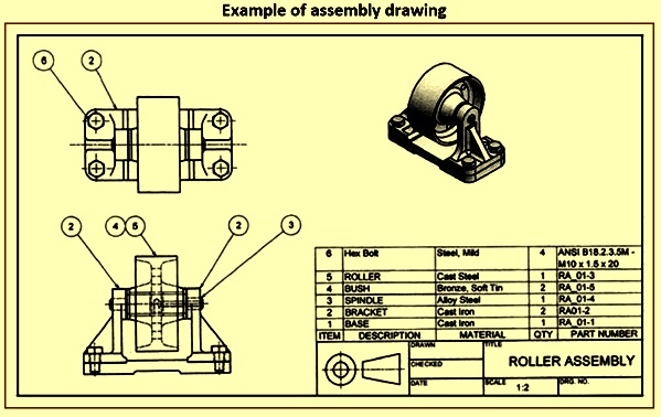
Assembly drawings demonstrate how all the individual parts shown in the detailed drawings fit together in the correct order. These drawings are essential for understanding the relationship between components and ensuring proper construction sequence.
The assembly drawing shows all parts in their final positions, with each component typically numbered for reference. Standard parts used in the assembly, such as nuts, bolts, or screws, are usually not drawn in detail but are listed in the parts list. The hollow rivets in the assembly are balloon-referenced, and the numbers refer to the parts list on the drawing or to corresponding numbers on the detail drawings.
Assembly Drawing Requirements:
- All parts must be shown in their final positions
- Each component should be clearly numbered
- Standard hardware can be referenced rather than drawn in detail
- Balloon referencing must be clear and unambiguous
Exploded pictorial views
Exploded pictorial views are commonly used in design presentations, catalogues, sales literature, and instruction manuals. These drawings separate components to show how they fit together, making the assembly process much clearer to understand.
The most common method for creating exploded views is isometric projection. These views provide a general impression of the parts of an assembly and demonstrate how they fit together. This drawing method is particularly effective at reducing the complexity of the assembly by showing the relationship between parts in a visual, easy-to-follow format.
Exploded views are particularly valuable in instruction manuals because they show the spatial relationship between parts that would be hidden in a standard assembly drawing.
Technical drawing standards and conventions
Dimensioning and chamfers
Proper dimensioning is crucial in working drawings to ensure accurate manufacturing. Chamfers, which are angled cuts that remove sharp edges, can often be very small and difficult to dimension in the normal way. When chamfers are not critical to design and function, they can be dimensioned using coordinate methods or special notation systems.
Critical Dimensioning Guidelines:
- All manufacturing dimensions must be clearly marked
- Chamfers require special dimensioning techniques when too small for standard methods
- Non-critical chamfers can use simplified notation
- Coordinate methods help with complex geometric features
Drawing presentation standards
All working drawings must follow recognised drawing standards to ensure professional presentation and clear communication. This includes:
- Proper scaling: Drawings must be drawn to appropriate scales that allow clear visibility of all features
- Clear dimensioning: All measurements must be clearly marked and easily readable
- Standard symbols: Use of recognised symbols and conventions throughout
- Title blocks: Professional formatting with proper title blocks and drawing information
- Line weights: Appropriate line thicknesses to distinguish between different types of information
Key features of effective working drawings
Working drawings should provide complete information for:
- Manufacturing requirements: All dimensions, tolerances, and specifications needed for production
- Material specifications: Clear indication of materials to be used for each component
- Assembly instructions: How components fit together and in what sequence
- Quality standards: Any special requirements or standards that must be met
- Reference information: Parts lists, detail references, and drawing numbers for organisation
The sectional view often clarifies an assembly detail, helping to show internal features that would otherwise be hidden. When balloon-referencing is used, care should be taken to place the circles in line and not to allow the leaders crossing each other, maintaining clarity in the drawing.
Key Points to Remember:
- Working drawings are the primary method for communicating complete design information clearly and accurately
- Three main types exist: detailed drawings (individual components), assembly drawings (how parts fit together), and exploded views (showing assembly relationships)
- All drawings must follow recognised technical standards including proper scaling, dimensioning, and professional presentation
- Detail extraction is used to show complicated areas separately at larger scales to avoid cluttering main drawings
- Exploded pictorial views are particularly useful for instruction manuals and help reduce the complexity of understanding how assemblies work together