Gear Basics (Leaving Cert DCG): Revision Notes
Gear Basics
Understanding gear fundamentals is essential for mastering dynamic mechanisms in Applied Graphics. Gears are mechanical devices that transmit motion and power between rotating shafts through the meshing of specially shaped teeth.
Understanding gear terminology
Gears have specific technical terms that describe their various parts and measurements. These terms are crucial for understanding how gears work and how to design them properly.
Mastering gear terminology is the foundation of all gear design and analysis. Each term has a specific technical meaning that affects how gears function together in mechanical systems.
Essential gear components
Addendum refers to the part of each tooth that extends outward from the pitch circle. This raised portion always equals the module value (), making it easy to calculate.
Dedendum describes the portion of each tooth that sits inside the pitch circle or pitch line. The dedendum measures 1.25 times the addendum (), providing necessary clearance between meshing gears.
Pitch Circle Diameter (PCD) represents the imaginary circle where gear teeth effectively mesh with another gear. This critical measurement determines the gear's size and is used in most gear calculations.
Key measurements and calculations
Module (m) serves as the fundamental measurement unit for gears. You can calculate it using the formula: .
Worked Example: Calculating Module
A gear has a PCD of 200mm and 20 teeth. Find the module.
Solution: Using the formula:
Therefore, the module is 10mm.
Circular Pitch measures the distance from one point on a tooth to the corresponding point on the next tooth, measured along the pitch circle ().
Pressure Angle defines the angle between the line of action and the common tangent to the pitch circles at the pitch point. Standard pressure angles are normally 20°, though 14.5° may also be used.
Perfect gears vs practical gears
In theory, perfectly smooth gears would touch at a single point and rotate without any friction between them. However, this creates practical problems in real-world applications.
When theoretical perfect gears mesh, there's no friction between the gear surfaces, which means they would slip against each other rather than transferring motion effectively. Real gears need specially shaped teeth that can grip and push each other to transmit power reliably.
Perfect theoretical gears cannot transmit power effectively because they lack the friction necessary to prevent slipping. This is why real gears require specially shaped teeth for reliable power transmission.
Gear ratios and speed relationships
The rotational speed relationship between two meshing gears depends on their relative sizes. When you have a large gear with PCD of 100mm meshing with a smaller pinion of PCD 30mm, the gear ratio becomes 2:1. This means the pinion rotates twice as fast as the larger wheel, but only applies when both gears share the same pressure angle and module.
Involute gears
Modern gear systems predominantly use involute-shaped teeth because they provide smooth, consistent motion transfer. The involute curve has special properties that make gears work efficiently.
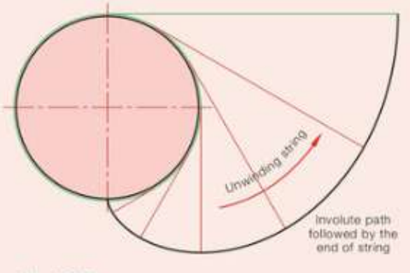
How involute curves work
An involute curve forms when you imagine unwinding a string from around a circle while keeping the string tight at all times. The free end of the string traces out an involute curve as it unwinds.
This mathematical curve has remarkable properties that solve practical gear problems. When two gears use involute-shaped teeth based on the same construction, their teeth mesh smoothly regardless of small variations in centre distance. This makes involute gears much more forgiving in manufacturing and assembly.
Involute gears are forgiving of small manufacturing errors and centre distance variations, making them the preferred choice for most modern gear applications. This tolerance reduces manufacturing costs and improves reliability.
Benefits of involute tooth design
Involute gears provide what engineers call "conjugate action" - this means the gears roll together smoothly without sliding or jamming. The specially curved tooth surfaces ensure consistent motion transfer throughout the meshing process.
The line of action (where contact between teeth occurs) runs tangentially to both gears' base circles, creating predictable and efficient power transmission.
The conjugate action of involute gears means that the velocity ratio remains constant throughout the meshing cycle, resulting in smooth operation and reduced vibration.
Practical gear applications
Identifying pinions and wheels
When two gears mesh together, the smaller gear is called the pinion while the larger gear is called the wheel. This distinction helps identify which gear drives which in mechanical systems.
Working depth and clearance
Working Depth represents the total depth that one gear tooth extends into the space between teeth on the meshing gear. This measurement equals the combined addendum and dedendum values.
Clearance provides essential space underneath each tooth when gears mesh. This prevents binding and allows for manufacturing tolerances, thermal expansion, and lubrication.
Proper clearance is critical for gear longevity. Insufficient clearance can cause binding and premature wear, while excessive clearance can lead to backlash and noise.
Key Points to Remember:
- Module calculation: - this is your most important gear formula
- Standard pressure angle: 20° is the most common, though 14.5° is also used
- Involute curves: Enable smooth gear meshing with conjugate action
- Gear ratios: Determined by comparing PCDs of meshing gears
- Addendum equals module: Always remember for standard gears