Intersection of Solids (Leaving Cert DCG): Revision Notes
Use of Auxiliary Plans
What are auxiliary plans?
Auxiliary plans are additional drawing views created to solve complex geometric problems that cannot be easily resolved using standard plan and elevation views alone. They are particularly useful when dealing with oblique surfaces or when you need to find the true shape of angled geometric features.
In technical drawing, auxiliary plans help us find accurate intersection lines between geometric solids, especially when these solids meet at angles that make direct measurement difficult from standard orthographic views.
Auxiliary plans are essential tools in technical drawing because they reveal information that remains hidden or distorted in standard orthographic views. Think of them as specialised viewing angles that unlock geometric solutions.
When do we need auxiliary plans?
Auxiliary plans become essential when:
- Working with oblique (slanted) surfaces that don't appear in their true shape in standard views
- Finding intersection lines between solids that meet at complex angles
- Determining the exact points where geometric shapes penetrate each other
- Measuring true distances and angles on inclined surfaces
The key principle is that auxiliary plans show surfaces in their true shape by viewing them perpendicularly (at right angles).
Basic construction principles
When constructing auxiliary plans, follow these fundamental rules:
Finding edge views: To see the true shape of an oblique surface, you must first create a view where that surface appears as a straight line (edge view). This auxiliary view is drawn perpendicular to the surface you want to analyse.
Projection methods: All points and lines are projected from the original views (plan and elevation) to the auxiliary plan using parallel projection lines. The distances and relationships between points must remain consistent across all views.
Critical Rule: Always establish the edge view of oblique surfaces before attempting to find intersections. This is the foundation of successful auxiliary plan construction.
Step-by-step construction method
Here's the systematic approach for using auxiliary plans to find intersections:
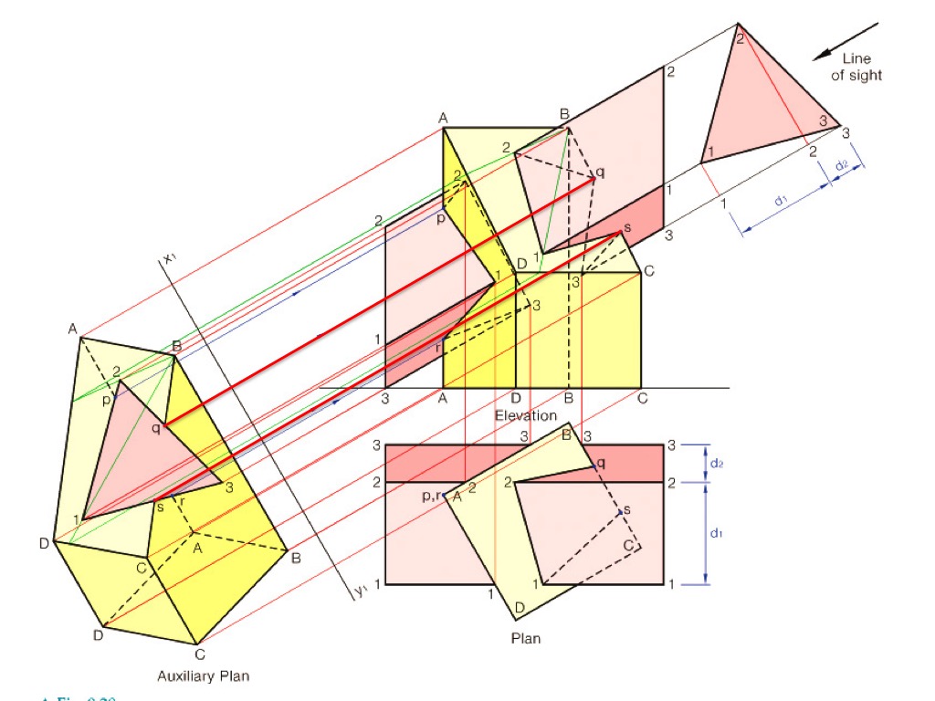
Worked Example: Complete Auxiliary Plan Construction
Step 1: Identify the problem Examine your plan and elevation views to identify which surfaces are oblique and where intersection lines need to be found. Look for areas where one geometric solid penetrates another.
Step 2: Create the auxiliary plan Draw the auxiliary plan perpendicular to the oblique surface. This will show the surface as an edge view, making it easier to identify intersection points. The auxiliary plan axis should be positioned to give the clearest view of the intersection zone.
Step 3: Project key points Transfer important corner points and edges from your standard views to the auxiliary plan. Use parallel projection lines to maintain accuracy. Each point in the original views must have a corresponding point in the auxiliary view.
Step 4: Find intersection points In the auxiliary plan, identify where the edges of one solid cross the surfaces of another. These crossing points represent the intersection line between the two solids.
Step 5: Project back to original views Once you've found the intersection points in the auxiliary plan, project these points back to your original plan and elevation views. This gives you the complete intersection line in all standard views.
Working with specific geometric problems
Square prism and triangular prism intersections
When dealing with a square prism intersected by a triangular prism, the auxiliary plan helps reveal the true shape of the triangular cross-section. This makes it much easier to identify exactly where the triangular edges penetrate the square prism surfaces.
Geometric Insight: The auxiliary plan transforms complex 3D intersection problems into clearer 2D analysis, where penetration points become immediately visible.
Oblique pyramid intersections
For pyramids meeting other solids at angles, auxiliary plans show the true shape of the pyramid's base and the actual angles of its faces. This clarity is essential for finding accurate penetration points.
Advanced construction techniques
Using edge views effectively
When you create an auxiliary plan that shows an oblique surface as an edge (straight line), you can immediately see which parts of other geometric shapes lie in front of, behind, or intersect with that surface.
Key Technique: The edge view is your most powerful tool - it instantly reveals spatial relationships that are unclear in standard views.
Surface contact analysis
Auxiliary plans help distinguish between surfaces that merely touch and those that actually intersect. True intersections create visible lines, while surface contacts appear as points or coincident edges.
Multiple auxiliary plans
Complex problems may require more than one auxiliary plan. Each auxiliary view reveals different aspects of the geometric relationship, building up a complete picture of how the solids interact.
Advanced Strategy: When dealing with multiple oblique surfaces, create separate auxiliary plans for each surface that needs analysis. This systematic approach prevents confusion and ensures accuracy.
Practical construction tips
Construction Best Practices
Accuracy is crucial: Use sharp pencils and precise projection lines. Small errors in auxiliary plans multiply when projected back to original views.
Work systematically: Don't skip steps in the construction sequence. Each stage builds on the previous one, so accuracy at each step is essential.
Check your work: Verify that points projected to the auxiliary plan make geometric sense. If something looks wrong, review your projection lines and measurements.
Label clearly: Mark all significant points with letters or numbers to track them through all views. This prevents confusion when projecting between different views.
Common applications in exams
Leaving Certificate DCG questions often test auxiliary plan construction through:
- Finding intersection lines between penetrating prisms
- Determining true shapes of oblique sections
- Calculating accurate angles and distances on slanted surfaces
- Solving complex geometric intersection problems
Exam Success Tip: The key to success is following the systematic construction method and maintaining accuracy throughout all projection steps.
Remember!
Key Points to Remember:
- Auxiliary plans show true shapes - They reveal oblique surfaces in their actual proportions and angles
- Edge views come first - Always establish the edge view of oblique surfaces before finding intersections
- Project systematically - Transfer points methodically between views to maintain accuracy
- Check intersections carefully - Verify that intersection points make geometric sense in all views
- Practice the sequence - Master the standard construction steps: original views → auxiliary plan → back to original views