Development and Interpenetration (Leaving Cert DCG): Revision Notes
Development and Interpenetration
What is development and interpenetration?
Development is the process of unfolding a three-dimensional curved surface onto a flat plane. Think of it like carefully peeling an orange and laying the skin flat - you're converting a 3D shape into a 2D pattern that shows all the surface area without distortion.
Interpenetration occurs when two solid objects intersect or pass through each other. The line where they meet is called the line of interpenetration. This is crucial in engineering and design when components need to fit together precisely.
The key to understanding both concepts is visualising how 3D objects relate to their 2D representations. Development creates flat patterns from curved surfaces, while interpenetration shows us exactly where different objects meet in 3D space.
Understanding interpenetration of solids
When two solids intersect, finding the exact line of interpenetration requires careful geometric construction. This process involves:
- Creating accurate plan and elevation views of both solids
- Identifying where the surfaces of each solid meet
- Plotting the intersection points systematically
- Connecting these points to form the complete line of interpenetration
The line of interpenetration shows exactly where one solid "cuts through" another, which is essential for manufacturing processes like welding, cutting, or joining components.
Critical for Manufacturing: The line of interpenetration isn't just a drawing exercise - it determines exactly where materials must be cut, joined, or modified in real-world manufacturing. Inaccurate interpenetration lines can result in components that don't fit together properly.
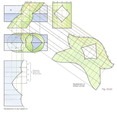
Development of curved surfaces
Developing curved surfaces is particularly important for cylindrical objects. The key principle is that a cylinder can be "unrolled" into a rectangular pattern. Here's how this works:
For cylindrical development:
- The height of the rectangle equals the cylinder's height
- The width of the rectangle equals the cylinder's circumference ()
- Any features or cut lines on the cylinder must be accurately transferred to the flat pattern
Worked Example: Cylindrical Development Method
Step 1: Draw the cylinder in plan and elevation views
Step 2: Divide the circular plan view into equal sections (typically 8 or 12 divisions)
Step 3: Project these division points to find their positions on the development
Step 4: Transfer heights from the elevation view to create the complete pattern
The result is a flat rectangular pattern that, when rolled up, recreates the original cylindrical form perfectly.
Step-by-step construction process
When solving development and interpenetration problems, follow this systematic approach:
Complete Construction Process
Step 1: Set up your views
- Draw accurate plan and elevation views of all solids involved
- Use a grid system to maintain precision
- Ensure all views are properly aligned
Step 2: Find intersection points
- Identify where the surfaces of different solids meet
- Mark these points clearly on both plan and elevation views
- Number the points for easy reference
Step 3: Connect the intersection points
- Join the numbered points to form the line of interpenetration
- This line shows the exact boundary where solids meet
Step 4: Develop the surfaces
- Unfold curved surfaces using geometric construction
- Transfer all intersection lines to the development
- Ensure accurate measurement and positioning
Step 5: Complete the solution
- Check all constructions for accuracy
- Add appropriate line weights and hatching
- Label all key features and dimensions
Key principles for success
Understanding the fundamental principles will help you avoid common mistakes and achieve accurate results.
Accuracy is essential: Small errors in construction can lead to major problems in the final solution. Always double-check measurements and projections.
Common Mistake to Avoid: Many students rush through the initial setup of plan and elevation views. Taking time to ensure these are accurate will save you from errors later in the construction process.
Work systematically: Number your construction points and follow a logical sequence. This prevents confusion and ensures you don't miss any steps.
Use proper projections: Understanding how orthographic projection works is fundamental to solving these problems correctly.
Think in 3D: While you're drawing on a 2D surface, always visualise what's happening in three dimensions to understand the relationships between different views.
Practical applications
Development and interpenetration techniques are used extensively in real-world engineering and design applications:
- Sheet metal work: Creating templates for cutting and forming metal components
- Packaging design: Developing box and container patterns
- Architecture: Designing curved roofs and complex building forms
- Engineering: Fitting pipes, ducts, and structural components together
- Manufacturing: Creating patterns for casting and fabrication
These techniques bridge the gap between theoretical geometry and practical manufacturing. Every curved metal duct, custom packaging design, or architectural feature you see has likely been developed using these principles.
Common exam techniques
Success in technical drawing exams requires not just understanding the concepts, but also applying effective drawing and presentation techniques.
Essential Exam Strategies:
Grid method: Use construction grids to maintain accuracy and make measurements easier to verify.
Colour coding: Different colours can help distinguish between different surfaces and construction lines.
Clear labelling: Number intersection points and label key features to make your solution easy to follow.
Line weights: Use appropriate line weights to distinguish between construction lines, object lines, and hidden details.
Remember!
Key Points to Remember:
- Development unfolds 3D curved surfaces into flat 2D patterns
- Interpenetration shows where two solids intersect or pass through each other
- Always work from accurate plan and elevation views using orthographic projection
- Use systematic numbering and construction methods to maintain accuracy
- Grid-based construction helps ensure precision in your solutions