Interpenetrations (Leaving Cert DCG): Revision Notes
Interpenetrations
What are interpenetrations?
In our daily lives, we frequently encounter situations where one solid object joins with or passes through another solid object. When this happens, we create what's called an interpenetration. This occurs when two three-dimensional objects intersect or penetrate each other, creating a line where they meet.
The key concept to understand is that when solids interpenetrate, they always produce a line of interpenetration at their junction. This line marks the boundary where the two solids meet and is crucial for technical drawing and design work.
The ability to visualise and accurately draw interpenetration lines is fundamental to technical drawing, engineering design, and architectural drafting. These lines help us understand how complex three-dimensional objects fit together in real-world applications.
Types of interpenetration lines
The appearance of interpenetration lines depends entirely on the types of surfaces involved in the intersection. Understanding this relationship is essential for predicting and drawing accurate intersections.
The type of interpenetration line you'll get is determined by the surface characteristics of the intersecting solids. This is a crucial rule that will help you predict the complexity of any intersection problem before you begin solving it.
Straight interpenetration lines
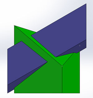
When solids that are made up of flat or plane surfaces are penetrated by similar solids (also with flat surfaces), the result is straight lines of interpenetration. This occurs because flat surfaces meeting other flat surfaces create linear intersections.
Examples of solids with flat surfaces include:
- Cubes and rectangular prisms
- Pyramids
- Wedges
- Any polyhedron (multi-sided solid)
Curved interpenetration lines
When solids with curved surfaces interpenetrate with other solids (whether curved or flat), the result is curved lines of interpenetration. This is because curved surfaces create more complex intersection patterns.
Examples of solids with curved surfaces include:
- Cylinders
- Spheres
- Cones
- Any solid with rounded surfaces
Method one: Limits method
For solving some of the less complex interpenetration problems, particularly those involving solids with plane (flat) surfaces, the Limits Method provides an effective approach. This method is especially useful when dealing with straightforward geometric shapes where the intersection patterns are relatively predictable.
When to use the Limits Method: The Limits Method is most effective for simpler interpenetration problems where you're dealing with geometric solids that have clearly defined flat surfaces. It's particularly useful for beginners learning interpenetration concepts because it provides a systematic approach to finding intersection lines.
The Limits Method works by identifying the start, end, and finish points of each interpenetration line. By finding these key limiting points, we can determine the full extent of how the solids intersect with each other.
Practical applications
Understanding interpenetrations is crucial for:
- Technical drawing: Accurately representing how objects join together
- Engineering design: Ensuring proper fit between components
- Architecture: Showing how structural elements intersect
- Product design: Creating realistic representations of assembled objects
Drawing interpenetrations
When drawing interpenetrations, always consider:
- The types of surfaces involved (flat or curved)
- The predicted line type (straight or curved)
- The method most suitable for finding the intersection
- The accuracy required for your specific application
Key Points to Remember:
- Interpenetrations occur when one solid penetrates or joins another solid
- Flat surfaces meeting flat surfaces create straight intersection lines
- Curved surfaces always produce curved intersection lines
- The Limits Method is effective for simpler interpenetrations with plane surfaces
- Always identify surface types first to predict the intersection line characteristics