Rotation and Inclination of Solids (Leaving Cert DCG): Revision Notes
Rotation and Inclination of Right Solids
Understanding right solids
Right solids are three-dimensional geometric shapes where their surfaces are parallel to the principal planes of reference (horizontal, vertical, and profile planes). When these solids are rotated or inclined from their standard position, we need special drawing techniques to represent them accurately in technical drawings.
The key concept here is that when a solid is moved from its normal orientation, we often need to create auxiliary views to show the true shape and size of the rotated or inclined surfaces. This is essential for accurate technical communication in design and construction graphics.
Auxiliary views become the foundation of technical drawing when dealing with rotated or inclined solids. Without them, we cannot accurately represent the true dimensions and shapes of surfaces that are no longer parallel to the principal planes.
Basic principles of rotation and inclination
When working with rotated and inclined solids, you'll encounter two main scenarios:
- Rotation: The solid is turned around a specific axis whilst remaining in the same plane
- Inclination: The solid is tilted at an angle to one of the principal planes
In both cases, the standard orthographic views (front elevation, end elevation, and plan view) may not show the true shape of all surfaces. This is where auxiliary elevations become crucial for accurate representation.
Remember that when surfaces are no longer parallel to principal planes due to rotation or inclination, the standard orthographic views will show foreshortened or distorted shapes. Only auxiliary views positioned parallel to these surfaces will reveal their true dimensions.
Drawing rotated cubes
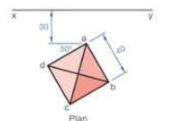
The cube provides an excellent starting point for understanding rotation principles. When a cube is rotated, its faces are no longer parallel to the principal planes, requiring careful construction techniques.

Worked Example: Constructing a Rotated Cube
The construction process follows these key steps:
- Draw the given plan - Start with the rotated square plan view
- Establish the axis of rotation - This becomes your reference line for projecting heights
- Create the auxiliary elevation - Project from the rotated plan to show the true shape
- Project back to standard views - Use the auxiliary view to construct the front and end elevations
The angle of rotation (often marked with ) determines how much the solid has been turned from its standard position. This angle is critical for accurate construction and must be maintained throughout all projections.
Working with tetrahedrons
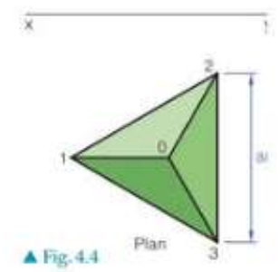
A tetrahedron is a triangular pyramid with four triangular faces. When the base is rotated about one of its edges, the construction becomes more complex but follows similar principles.
Worked Example: Tetrahedron Rotation Construction
The construction method involves:
- Drawing the rotated triangular plan - Show the base triangle in its new position
- Establishing the rotation edge - This edge remains fixed whilst the opposite vertex moves
- Projecting heights from the auxiliary view - Use construction lines to transfer measurements
- Completing all orthographic views - Ensure consistency across front elevation, end elevation, and plan
When a tetrahedron is rotated about edge 1,3, the construction requires careful attention to which points move and which remain fixed. The vertex opposite to the rotation edge follows a curved path that must be accurately plotted.
Square-based pyramid projections
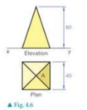
Square-based pyramids present another common scenario in rotation and inclination problems. When the base surface lies on the horizontal plane, the pyramid appears in its true shape in the plan view.
Worked Example: Square-Based Pyramid Projection
The key steps include:
- Project the views from the auxiliary - Transfer all key points using parallel projection lines
- Maintain proportional relationships - Heights and widths must remain consistent
- Use construction geometry - Semi-circular arcs help establish correct positions
- Project between standard views - Ensure front and end elevations align with the plan
Remember that when surfaces are parallel to principal planes, they appear in their true size and shape in the corresponding orthographic view.
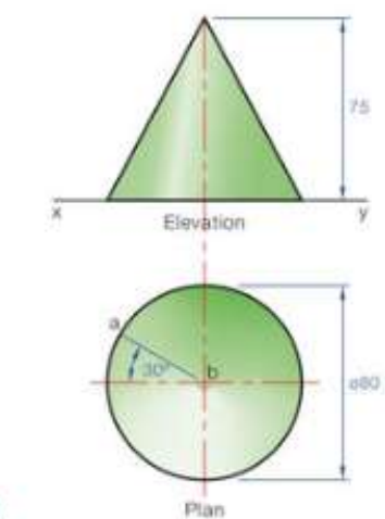
Cone rotation techniques
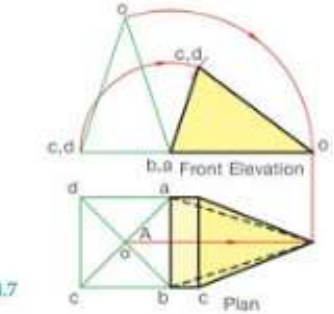
Cones require special attention when rotated or inclined because of their curved surfaces. The generator (straight line from apex to base circumference) becomes crucial for construction.
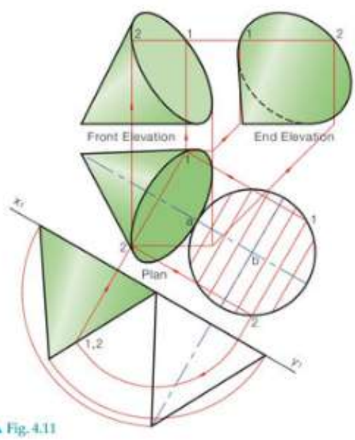
Worked Example: Cone Projection Technique
For cone projections:
- Draw the plan with base on horizontal plane - The circular base appears as a true circle
- Create auxiliary elevation parallel to the generator - This shows the cone's true profile
- Divide the base into parts - Use systematic point division for accuracy
- Project through all views - Maintain consistent point relationships
When the cone's generator is at to the horizontal plane, the auxiliary view becomes essential for showing the true triangular profile of the cone's side.
Advanced pyramid constructions
Pentagonal-based pyramids demonstrate more complex rotation scenarios where multiple surfaces must be considered simultaneously.
Worked Example: Pentagonal Pyramid Construction
The construction principles remain consistent:
- Draw the given plan and project end view - Establish the basic orthographic relationship
- Surface analysis - Determine which surfaces are parallel to vertical planes
- Rotate until surface is vertical - Use the auxiliary view to achieve the required orientation
- Project remaining views - Complete the orthographic set from the auxiliary construction
For pentagonal pyramids, when surfaces are parallel to the vertical plane, they appear as true shapes in the front or end elevation views.
Construction techniques and tips
Essential construction methods
Fundamental Construction Principles
- Always use construction lines to connect corresponding points between views
- Maintain consistent scale across all orthographic projections
- Number or label key points to avoid confusion during complex constructions
- Use auxiliary views when standard views don't show true shapes
Common mistakes to avoid
Critical Errors to Avoid
- Forgetting to project heights accurately between views
- Not maintaining the correct angle relationships during rotation
- Mixing up which surfaces are parallel to which planes
- Rushing the construction without proper planning
Exam success strategies
Strategies for Success
- Practice with different solid types - cubes, pyramids, cones, and prisms
- Master the auxiliary view technique - this is essential for rotation problems
- Understand the relationship between rotation angles and auxiliary view positions
- Check your work by ensuring all views are consistent with each other
Remember!
Key Points to Remember:
- Right solids have surfaces parallel to principal planes, but rotation changes this relationship
- Auxiliary views are essential when standard orthographic views don't show true shapes
- Construction lines must connect corresponding points accurately between all views
- Rotation angles determine the orientation of auxiliary views and must be maintained throughout
- Practice with different solid types builds confidence and improves construction speed